|
 |
 |
 |
|
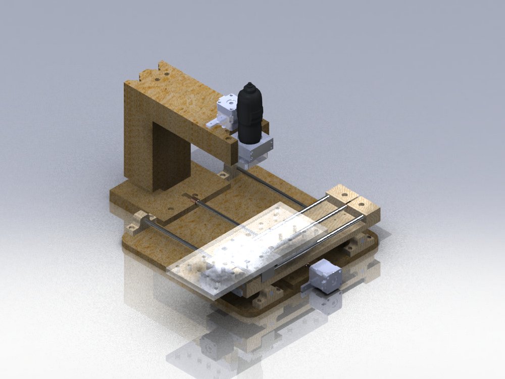
This is the micromill cnc machine that I built
in summer of 09. Click here to go
to project
3D PDF |
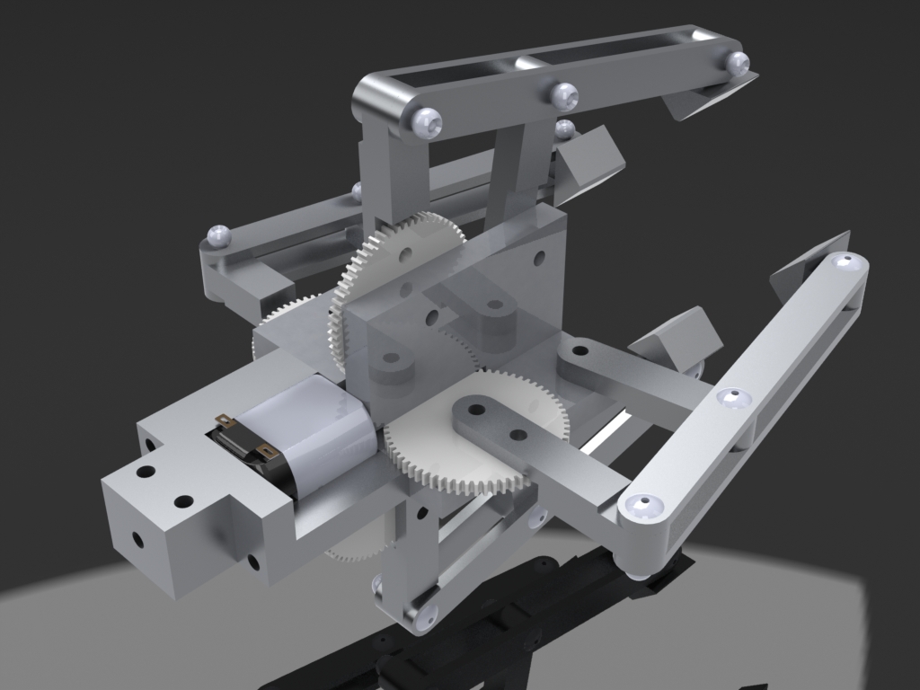
This is a claw that is designed to go into a
Claw grabber game. It was ultimately built and used in the designated
project. 3D PDF |
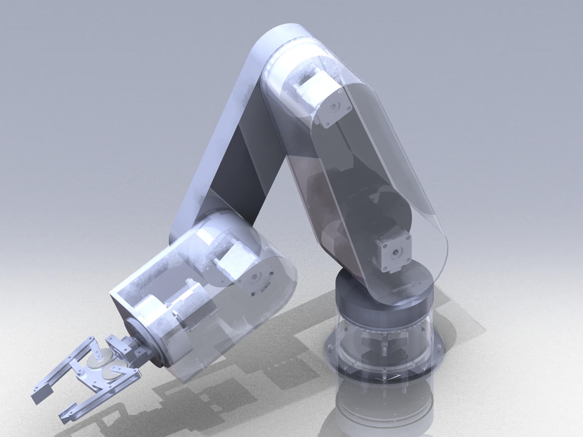
This is a robotic arm I designed for a
potential class project, but ultimately the team decided to no use the
design. 3D PDF |
|
 |
 |
 |
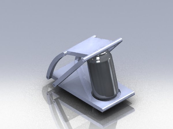
| This was a potential idea for a mechanical
design project. The design uses a 4-bar linkage mechanism to crush cans.
3D
PDF |
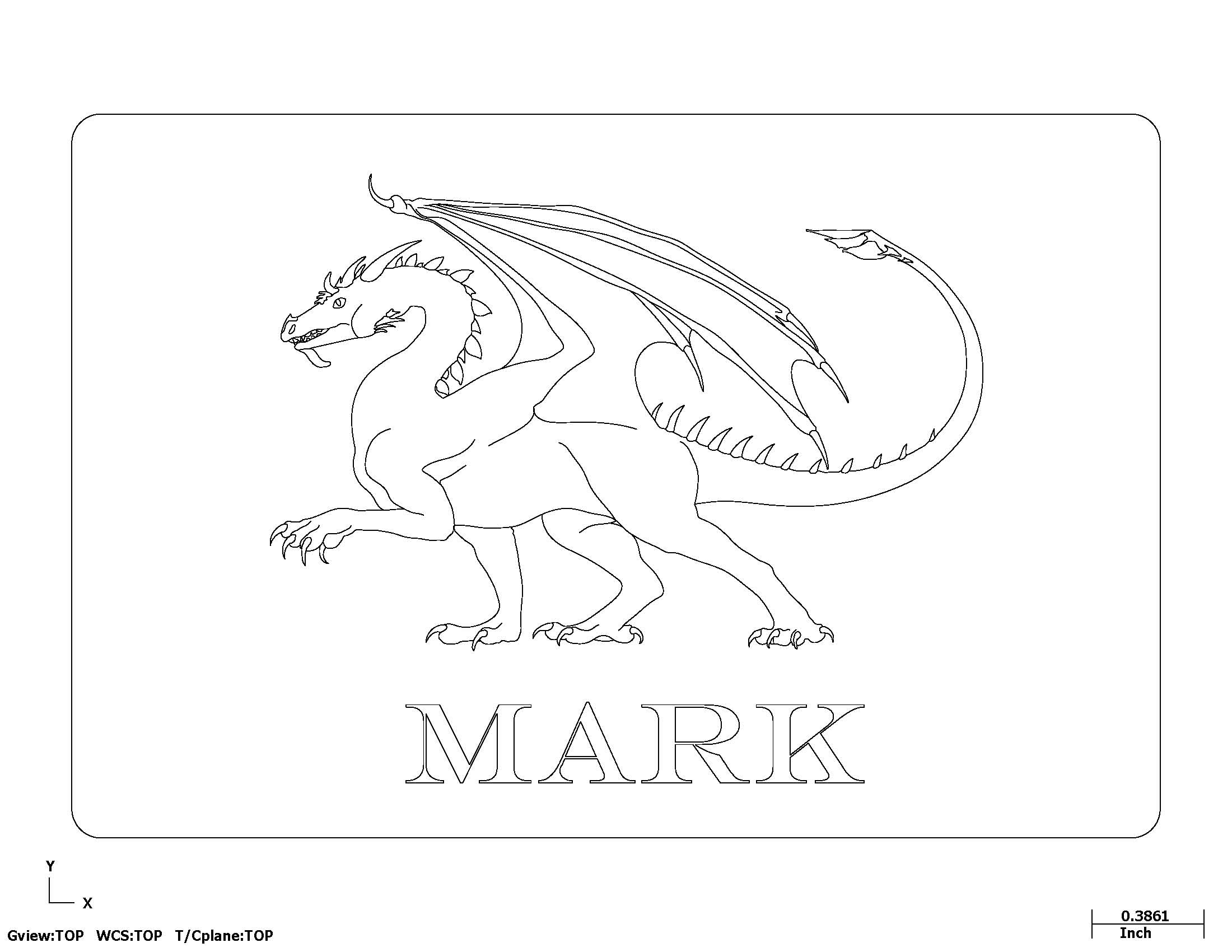
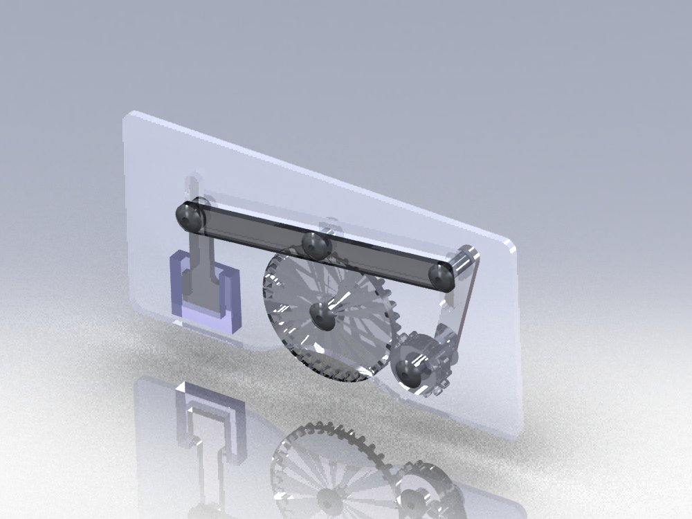
This is a mechanically functioning name card
that I was working on. 3D PDF |
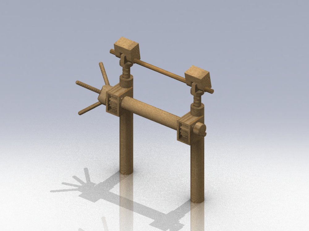
This is the solid oak geared lifters that was
designed for a class project. Click here to
go to project 3D PDF |
|
 |
 |
 |
| This is a manometer that was build for a fluid
mechanics project. |
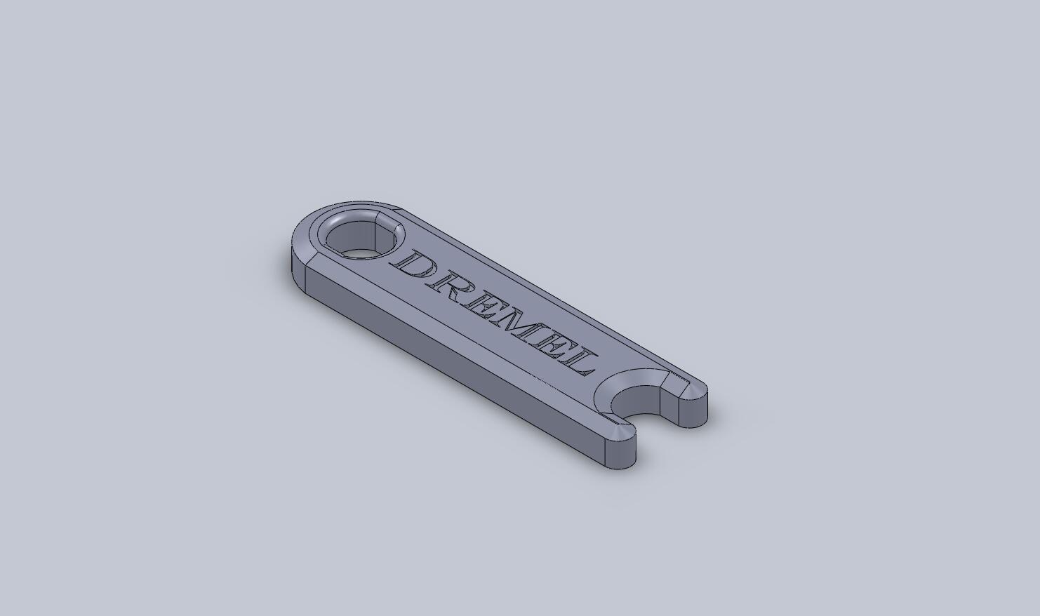
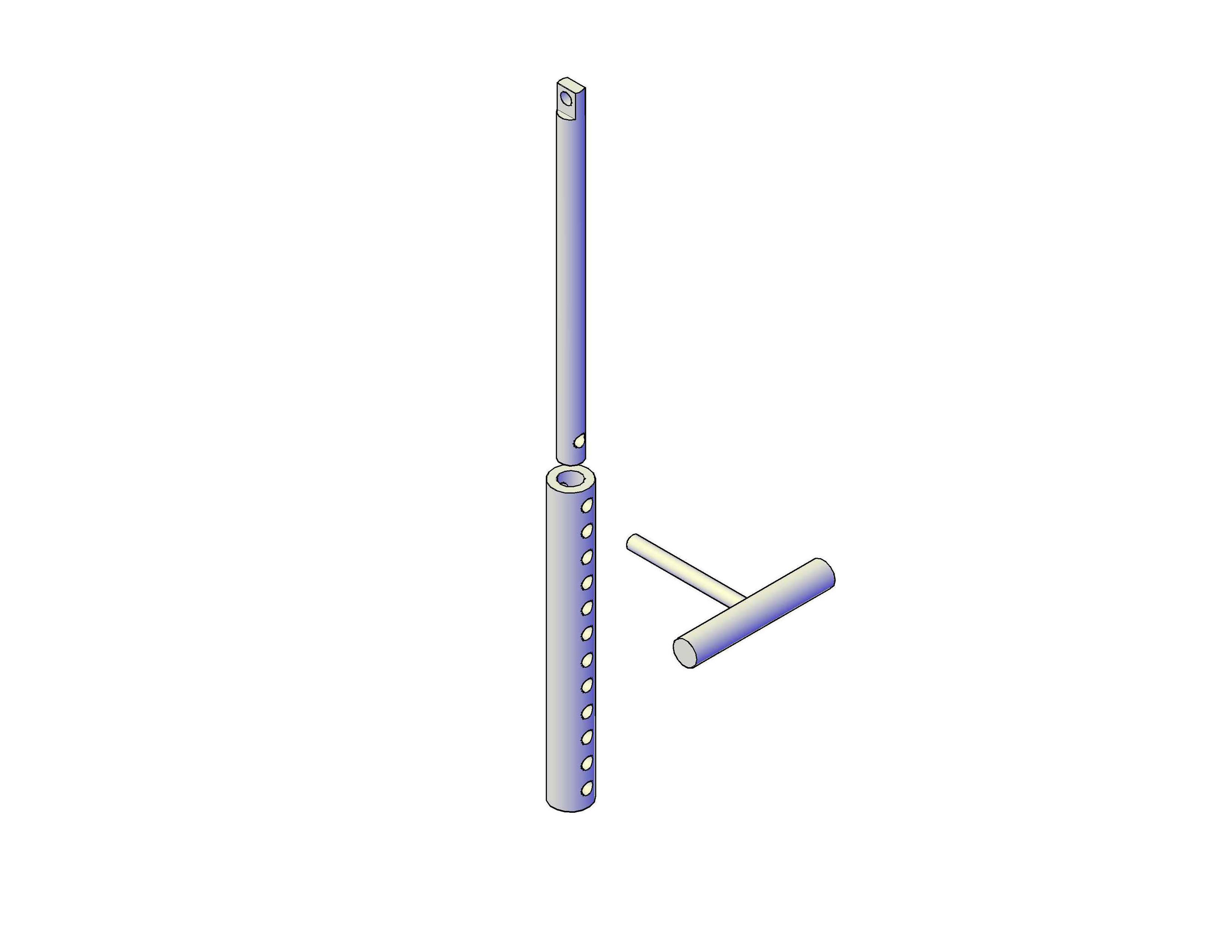
This tool was built to make it easier to change
bits on the Dremel of my MicroCNC. |
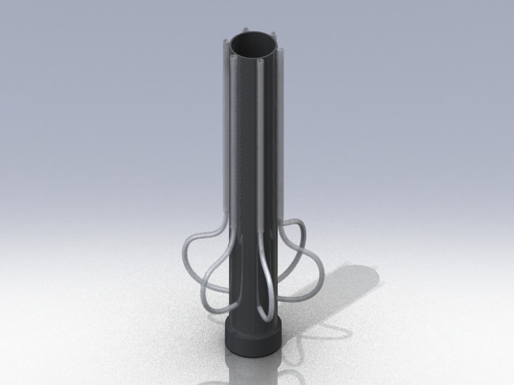
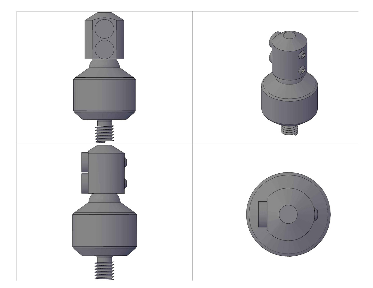
This is a manual direct drive encoder for a
Unipolar stepper motor that I designed using a shell of an old DC motor.
Click here for the Animation |
|
 |
|
|
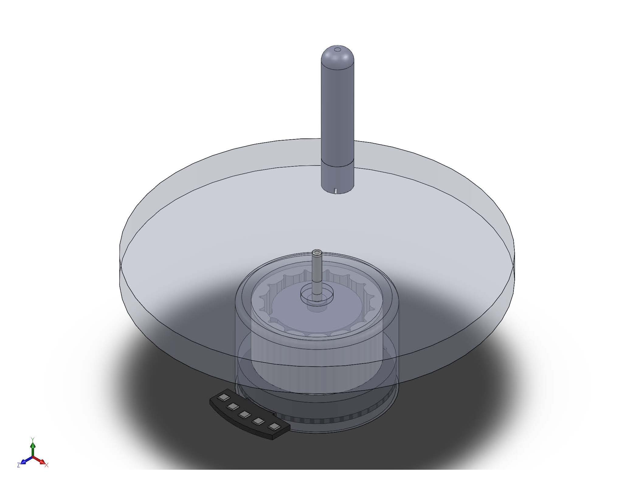
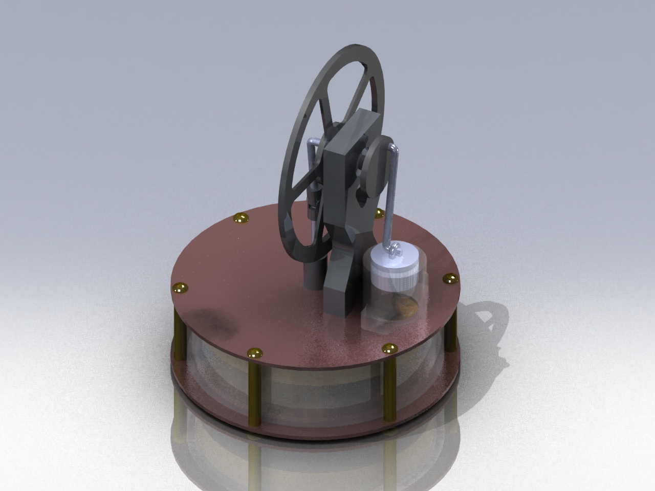
| This is a Stirling engine that i designed with
the possibility of building it in the near future. |
|
|
|
 |
 |
 |
|
This is a center bushing that I drew for a class assignment. It is
dimensioned and sectioned for various views. |
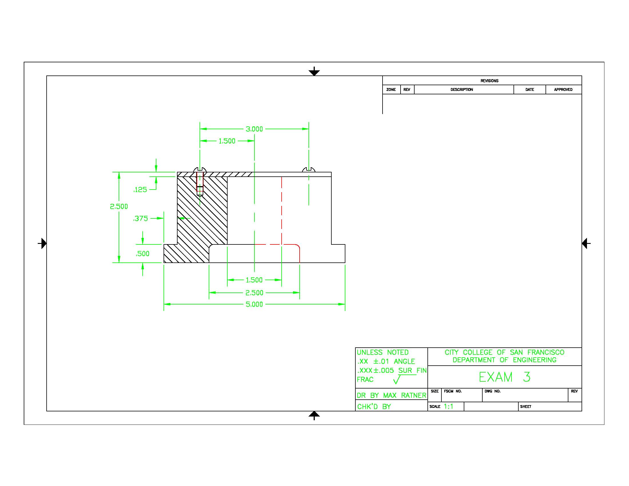
This was an in-class exam that was assigned for Engineering drafting class. |
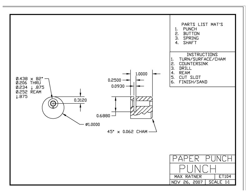
This is a hole punch body that I drew up that was fabricated in my
engineering technology class. It was fabricated from raw aluminum stock. |
 |
 |
 |
| This is the first design of the oak lifter but
it was redesigned to get a more accurate adjustment. |
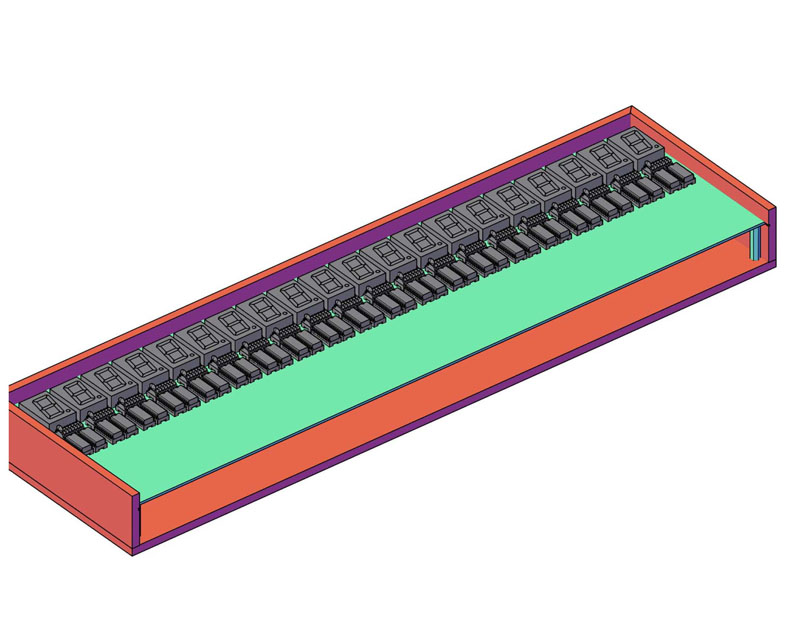
This is a dooms day timer (counts to sun's
death) that was designed and built by me and a fellow classmate for a
display case. |
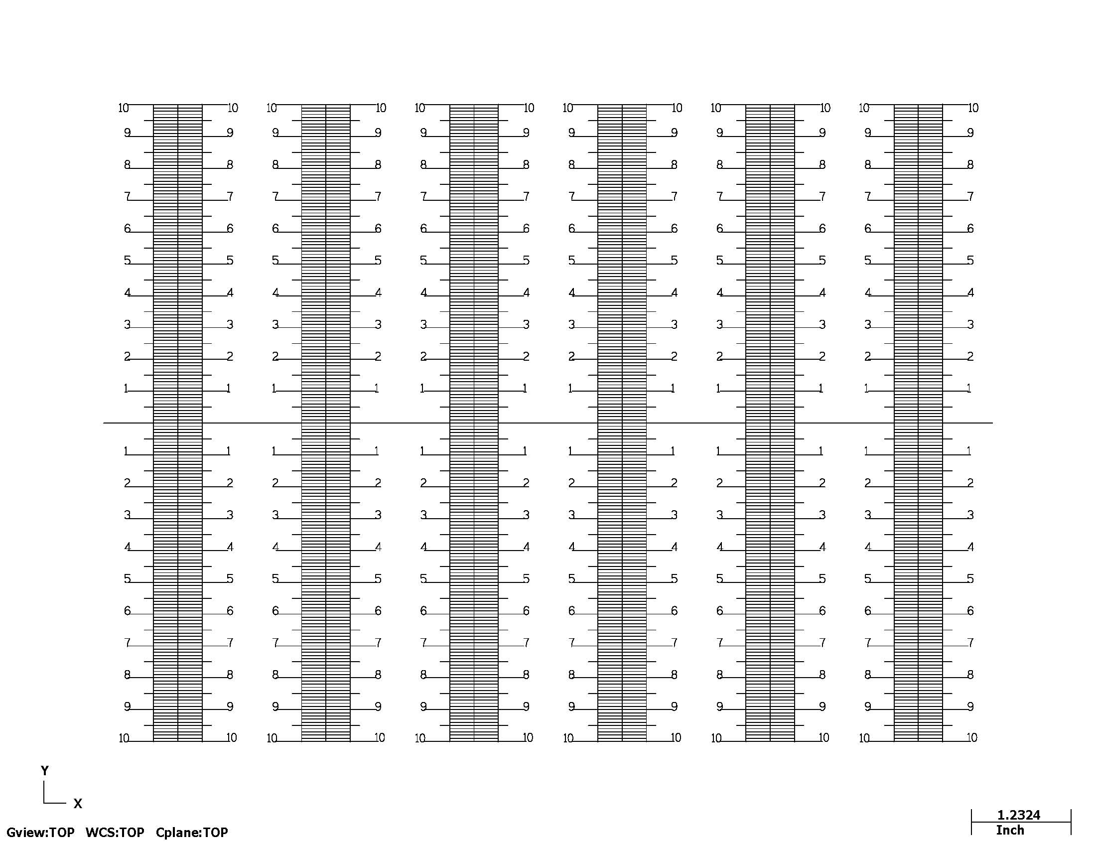
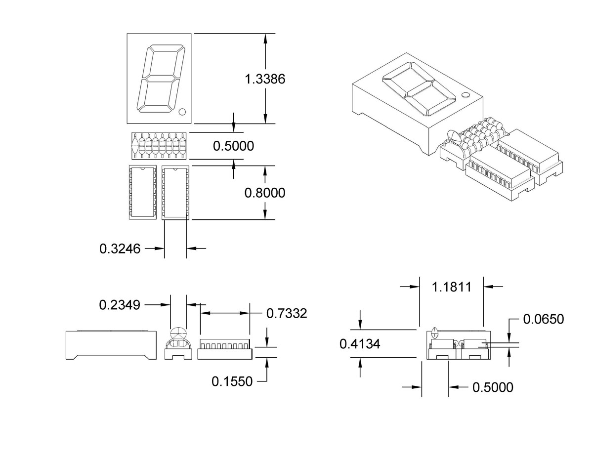
This is the layout and dimensions of a single
circuit |
|
 |
 |
 |
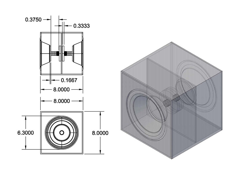
| This is a speaker box that I built in a special
projects class. The objective was to make functioning speakers out of paper
plates. |
This is an adjustable cooling nozzle for
machining on a lathe. |
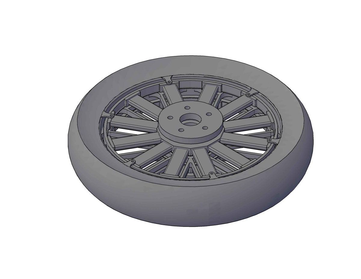
This is conceptual design of mine of a electric
motor/wheel combination for a motorcycle. |
|
 |
 |
 |
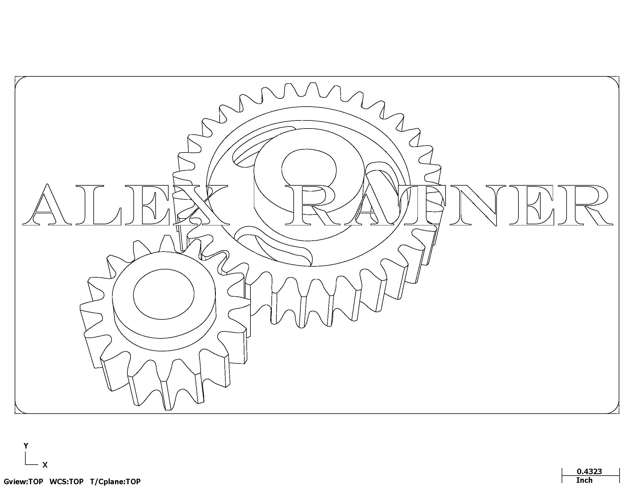
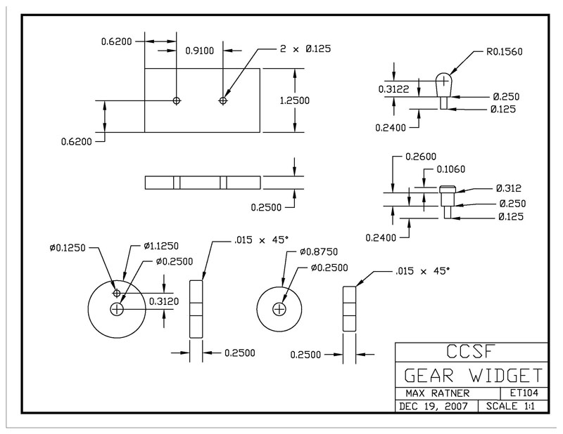
| This is a gear widget that was made in a
manufacturing class. |
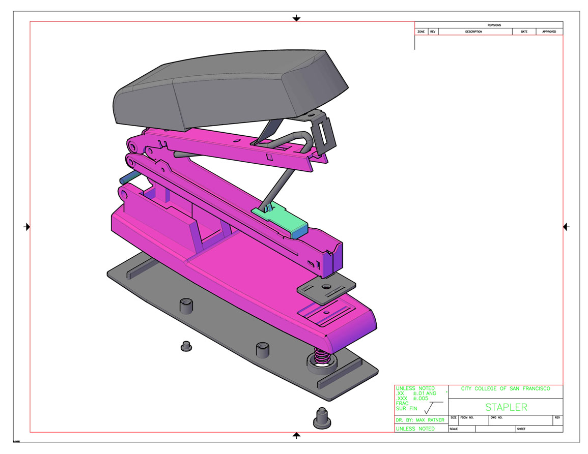
This was a final project for my AutoCAD class.
I used an existing product and did a CAD representation. |
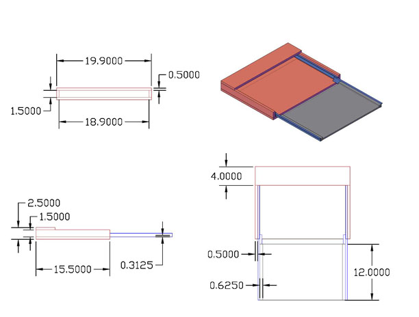
I had designed and built a pull out drawer for
my mother so that she would not have to scoot her chair in to eat. |
|
 |
 |
 |
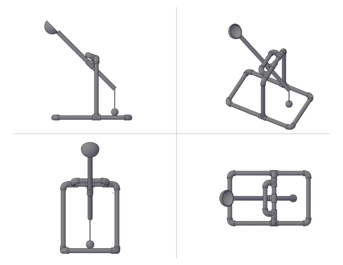
| This is a trebuchet that was designed as a
class project to launch projectiles. Materials were limited to PVC piping
and a lead fishing weight. |
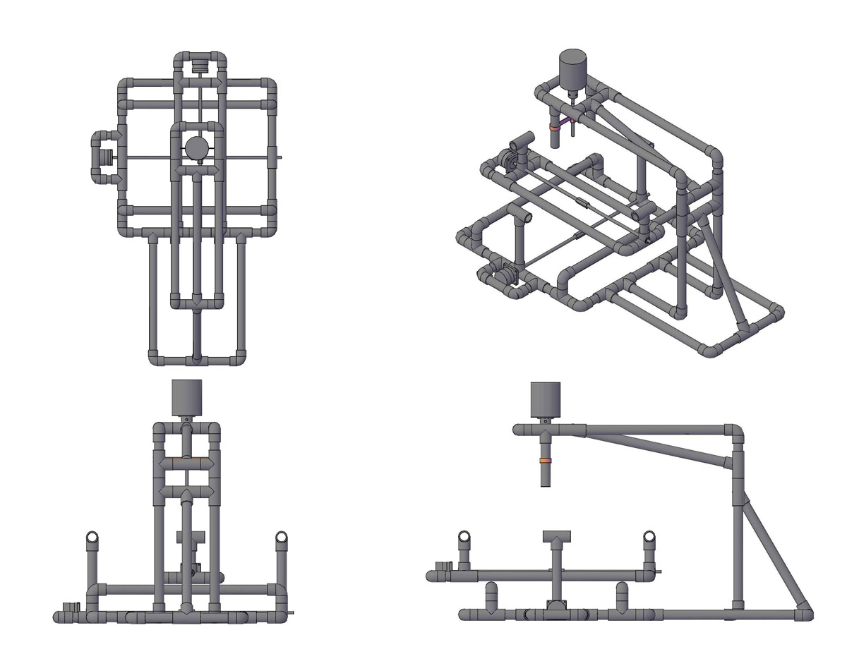
This is the first version of the design of the
CNC that I had built as a class project, but upon construction the
instability of PVC was apparent. |
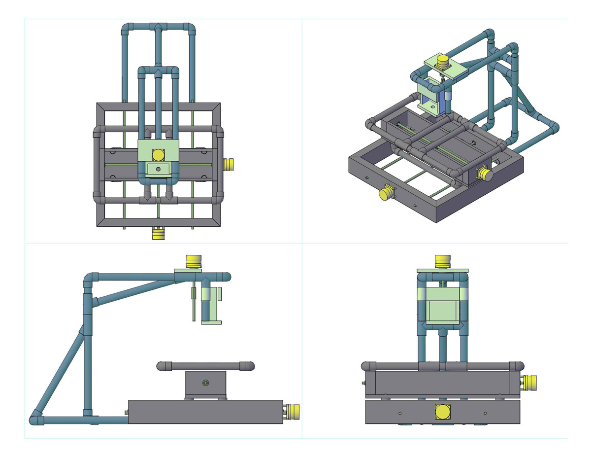
This is the second design of the CNC with a
wooden base. Click here to go to project |
|
 |
 |
 |
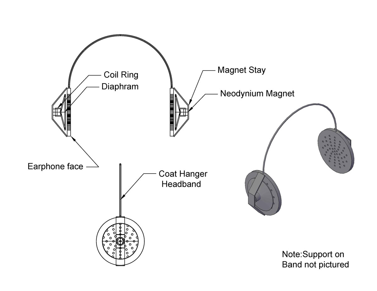
| This is a set of headphones that I made based
off of a cheap working paper plate speaker project.
Click here to go to project |
This is my bottle rocket design that I did to
help a fellow classmate with their project. |
This is a back end of a boat that I was helping
to make an auto centering steering design for the rudder. |
| |