 |
|
|
|
|
3 Axis CNC Mill Project In an Engineering Lab/Club (ENGN 48L) classroom, me and a classmate (Skot) decided that it would be interesting to build a fully functional CNC machine in order to be able to fabricate our own circuit boards among other things. |
|
|
|
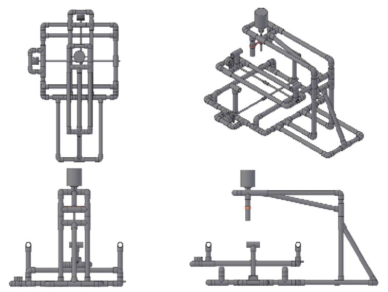
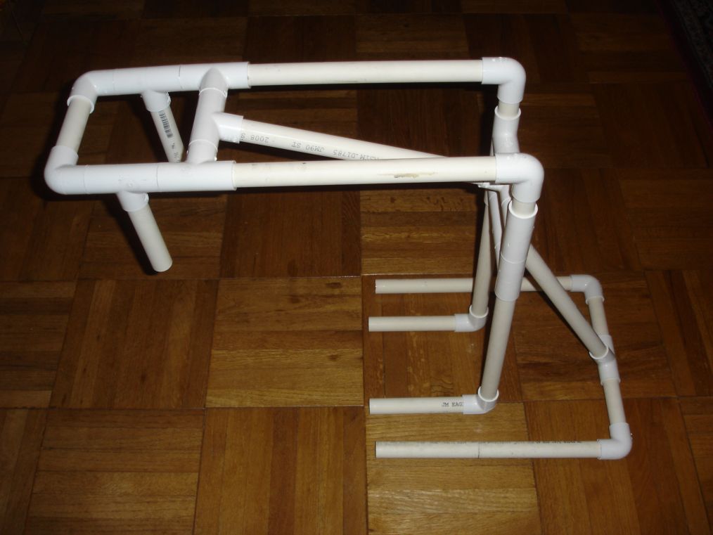
This is the first idea of the low budget CNC machine since we had access to plenty of pvc pipes this would have naturally been the building material of choice for the budget that we had. So to have something to work with I made an Autocad drawing for us to follow. Due to pvc's flimsy nature over any kind of decent length we opted out for something more sturdy. |
|
|
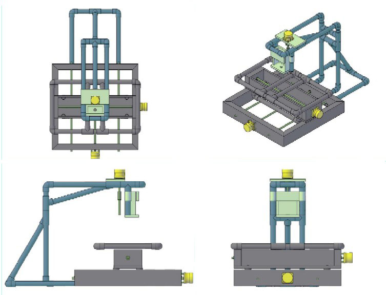
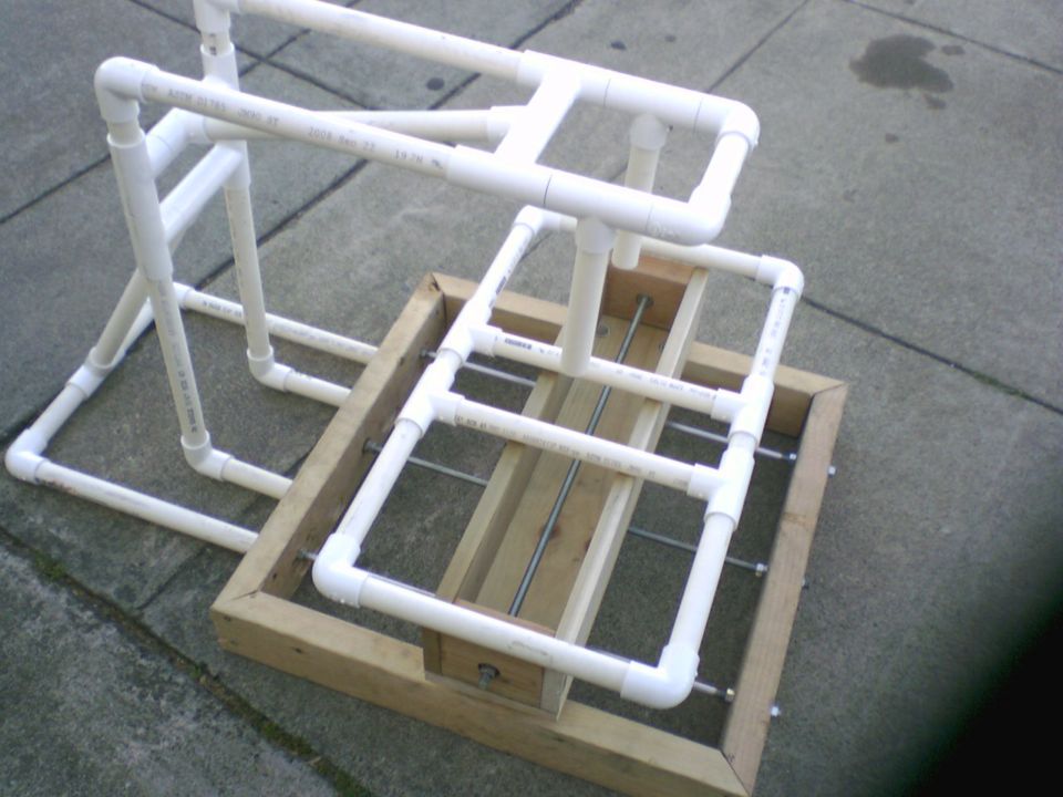
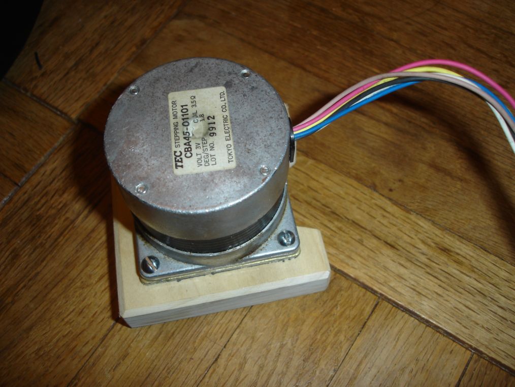
After the reworking the Autocad drawing so that 2x4 is used for the base instead of the previous entirely pvc body. the building of the machine finally went underway. We acquired 3 stepper motors from old printers that were in a old box full of spare parts at school. We bought some 2 foot threaded rods at Home Depot as well as some coupling nuts to act as the driving nuts. After a little bit of time with an arc welder I got the coupling nuts attached to some steel plate so that we could bolt it to the Y axis.
|
||
|
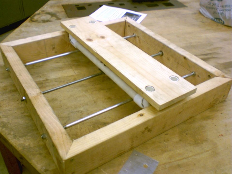
After some wood cutting and drilling we managed to get the wooden base together as well as make the base for the Y axis.
|
||
|
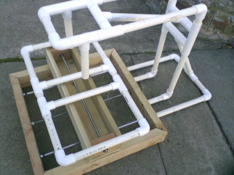
Several hours with a pipe cutter and following the Autocad drawing exactly the frame for the Z axis starts to come together. That is where I noticed the major flaw of using PVC as a sturdy building material.
|
||
|
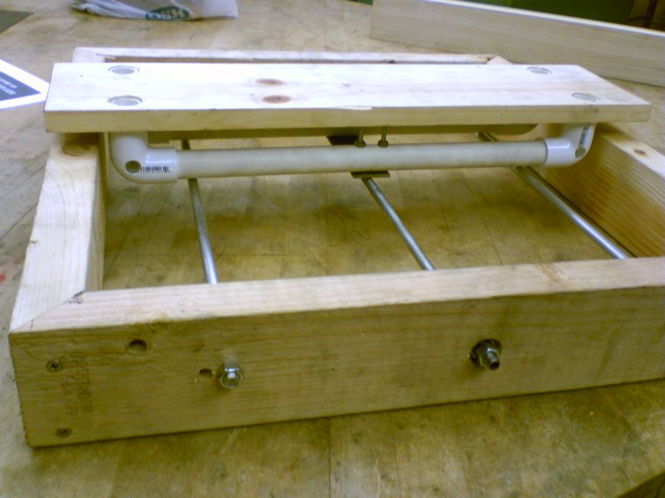
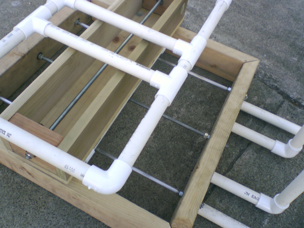
I drilled 4 holes measured precisely so that there wouldn't be any problems inserting the Z axis frame. After some gentle taps with a hammer the pvc slid right in to the holes cut out for it. The sturdy wooden frame helped reinforce the Z axis but i knew that something had to be done to further strengthen it.
|
||
|
After experimenting with the idea of using a laser to cut various designs as well as engraving we decided to go with the tried and true dremel based CNC. This is the dremel mount, which is constructed out of poplar wood with 4 bolts with wing nuts on the back for quick release of the dremel when a bit needs to be changed. As you can see the spindle is almost flush with the bottom of the .75" thick wood.
|
||
|
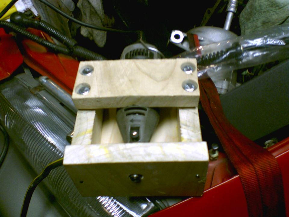
This is the spacer needed to stand off the motor from the base. As you can see there is a slot in the spacer this is so that we can attach the motor before the spacer goes in; allowing us the maximum working area for the attachment of the motor to the driving rod. This is the Autocad file for the spacer and the spacer for the Z axis (not pictured)
|
||
|
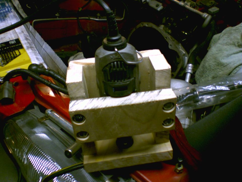
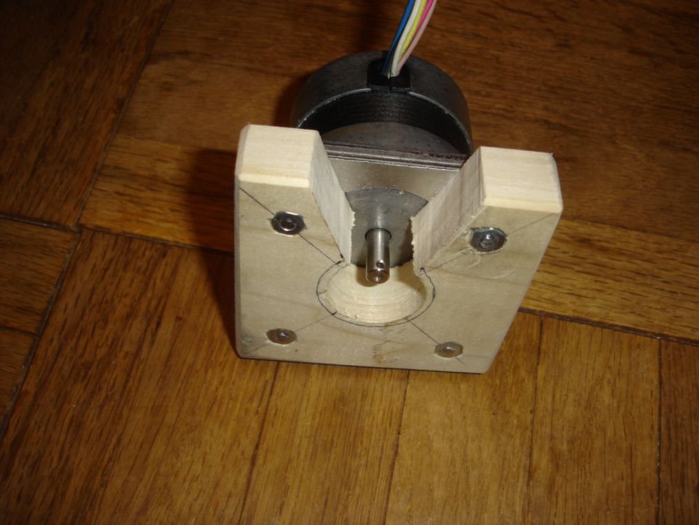
This is the motor attached with nuts and bolts to the spacer there still needs to be holes drilled on the corners of the spacers so that we can screw it directly into the wooden base.
|
||
|
As the cheapest and quickest solution to the wobbling of the Z axis I decided that sandwiching the pvc pipes between plywood would provide a decent amount of strength. So once the pieces were cut to the right shape I screwed it together with some 3 inch long wood screws. You can see that the dremel mount is already attached with the driving rod connected to it as well.
|
||
|
Once all the plywood is attached everything is once again reassembled and after some more welding the coupling nut is attached to some 1/8" steel. This is so that the table frame can be attached to the setup.
|
||
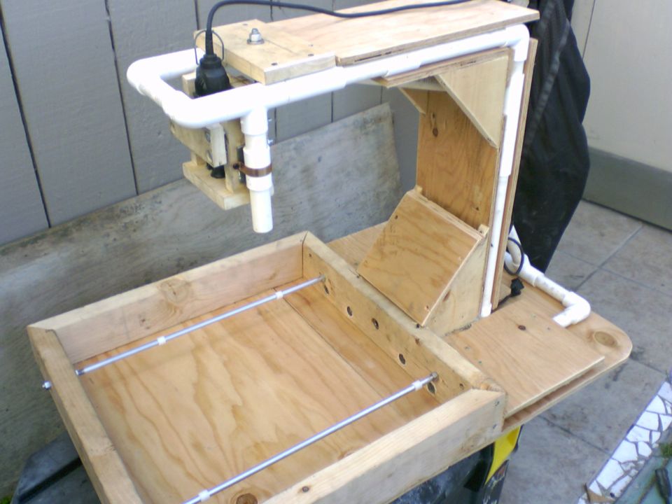
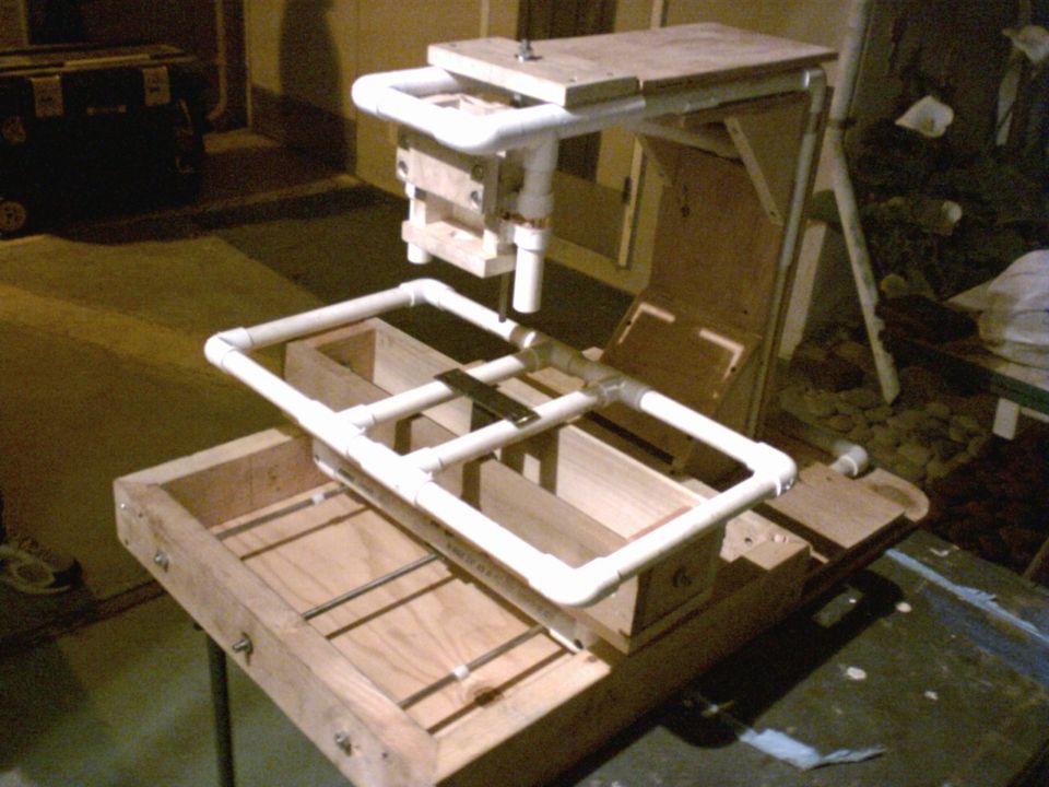
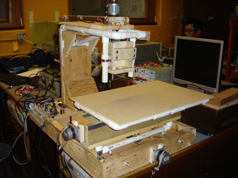
| Once we get all of the pieces together in one place and add everything that me and Skot worked on separately together we have a working machine. We add all of the motors for the X, Y, and Z axis and add the wooden table top to the PVC frame. I make the L brackets for all of the limit switches which at this time are momentary SPST switches with a very light action/short travel press. | ||
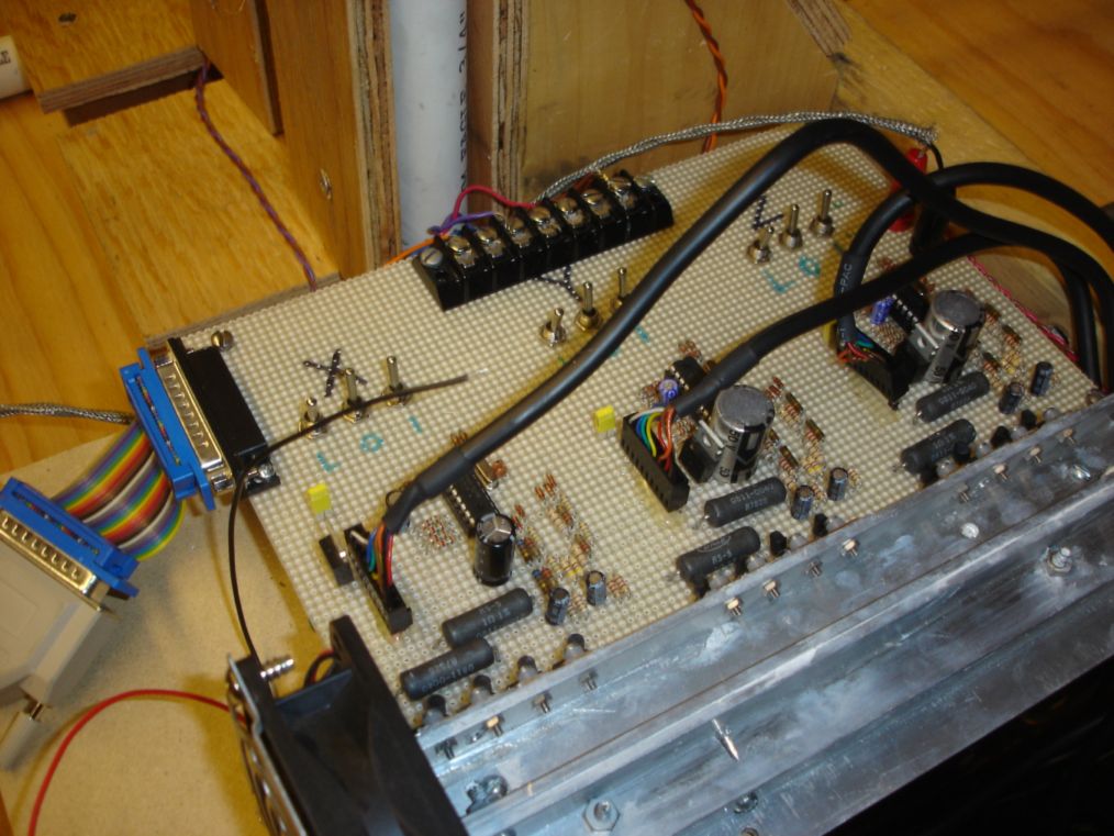
| This is the driver board that skot built which has the X, Y, and Z driver clearly labeled on the board itself. The row of inputs at the end of the board are for the limit and homing switches which interface directly into the attached parallel port. The program we chose to run the machine is the demo version of Mach 3. which makes for a nice CNC control software. | ||
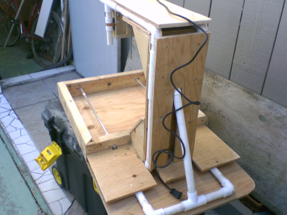
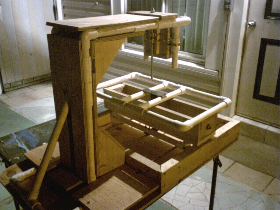
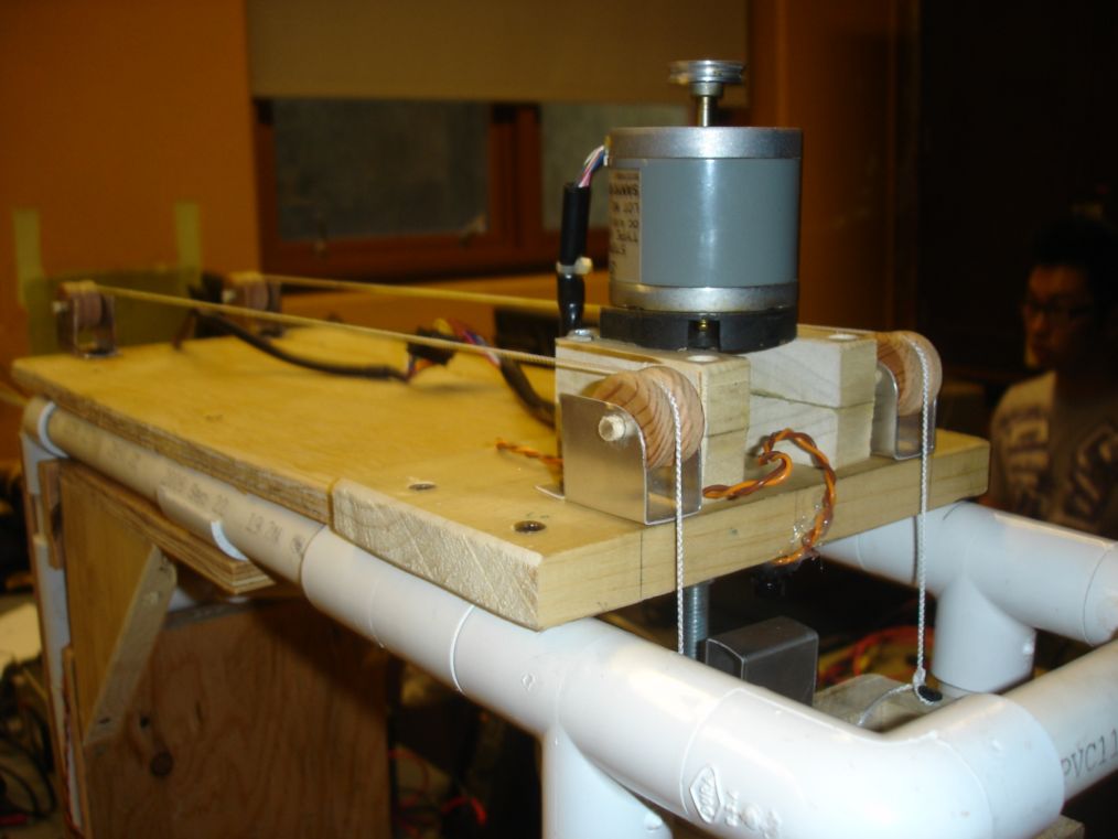
| As you can see the we made some pulleys to counteract the weight of the dremel mount to reduced the power that the Z axis stepper has to output. We made the pulleys by using a hole saw to cut out the general round shape then sticking it in a drill press and using a file to carve a nice smooth groove down the middle to keep the string in place. There is a lead weight attached to each of the strings to provide even pull to both left and right sides of the mount. | ||
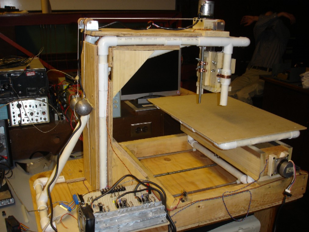
| This is the completed project we still need to make some adjustments and tests, but overall it is successful. eventually we might replace the guides with something that reduces the wobble as well as the friction acting on the X/Y axis. | ||
|
|
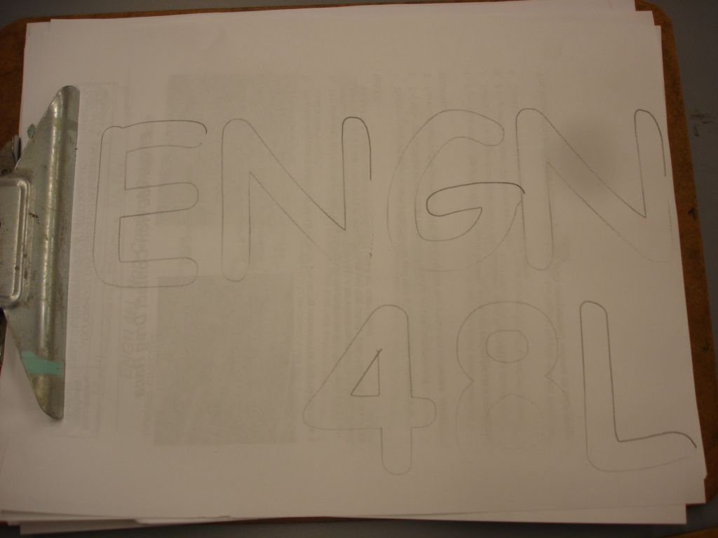
This is some samples of the machine making some drawing as well as engraving/cutting of some MDF. It reads out ENGN 48L, in comic sans font, which is the class that we made this project in. | |
|
The pencil drawing came out pretty well but due to not being secured to the dremel holder that is attached to the motor the pencil kept having to be pushed down so this resulted in a not very even line thickness throughout the drawing. | |
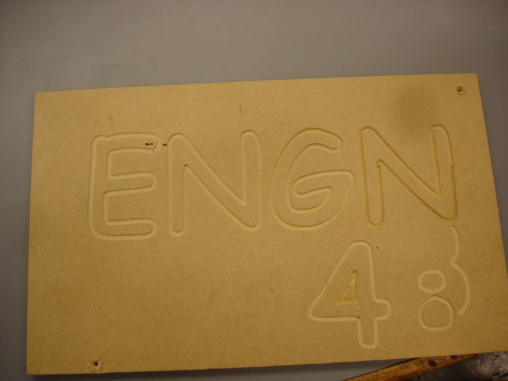 |
This is the result of the dremel engraving some MDF of the same sign as the one above. As you can see it started to skip steps near the end we beleive this is due to overheating in either the driver or the motor. Some tuning still needs to be done before the CNC is 100% done. | |