 |
|
|
|
|
3 Axis CNC Micro Mill A summer '09 project I decided to undertake, is a more precise CNC mill that I could use and take with me if needed. Once again my budget is constrained but I believe that with careful planning and use of accurate but low cost parts would allow me to afford such a project for the summer. Having increased my knowledge in generating G-code to run the machine I needed something to "play" with so that I could get a full experience of CNC machining.
|
|
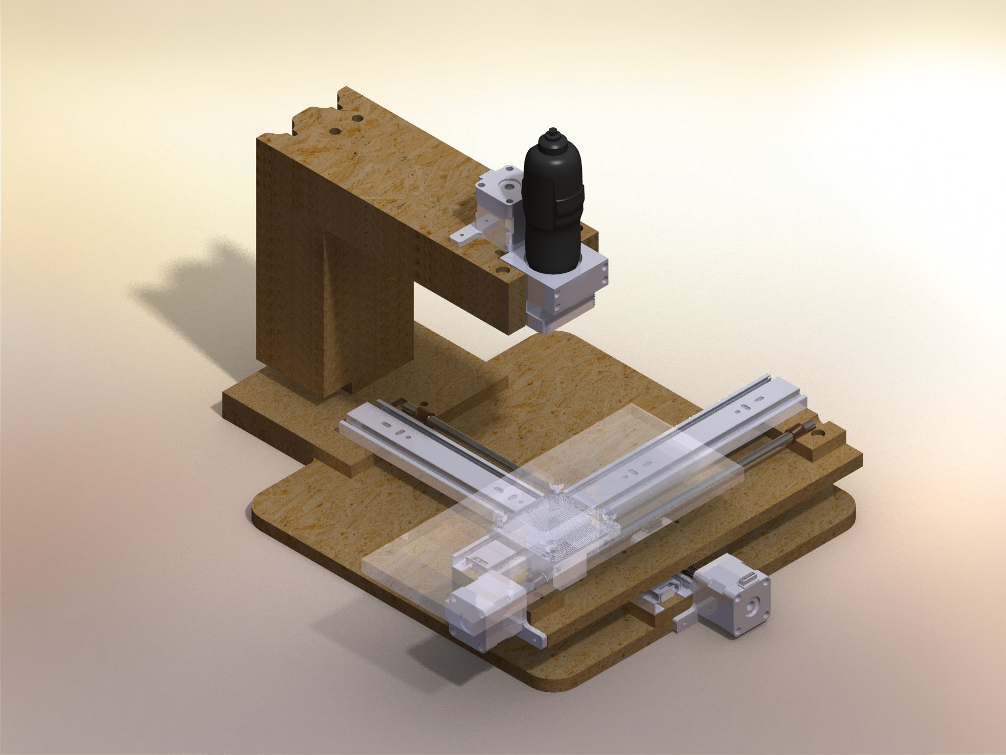 |
The first step to making a successful design is to have an accurate representation of it in a CAD or CAM software. In my eagerness to expand my Solidworks knowledge that is the CAD software that I chose. At this point I decided on the materials which I would use. -12" heavy duty drawer slides from Home Depot for a pair- $10 -3'x'4' x .5" MDF sheet from Home Depot-$8.50 -Nema 17 Steppers (Minebea 17PM-K103-24V) from Ebay - $5-$7 each plus shipping -3/8" threaded acme rods I got from Wholesale Tools - $3.90 each plus shipping -I had some 3/8" Polycarbonate lying around that I could use for the table surface. -I managed to acquire some scrap aluminum for the remainder of the parts. -the linear guide bar for the Z axis I got off of an old printer so the running total for the design so far comes out to be roughly $65.30 The work area came out to be 9.5"x9.5"x2"(with a 1 inch long bit) here are the complete Solidworks plans compressed- 4.2 Mb (these design plans changed please look below for the updated plans) A free Solidworks file viewer can be downloaded here |
|
| I decided to animate some motion of the finished design so that it gives a better idea of what it's limits are and how far the rails stick out past the base of the unit. As you notice this unit is designed to use a Dremel mounted to the machine. | ||
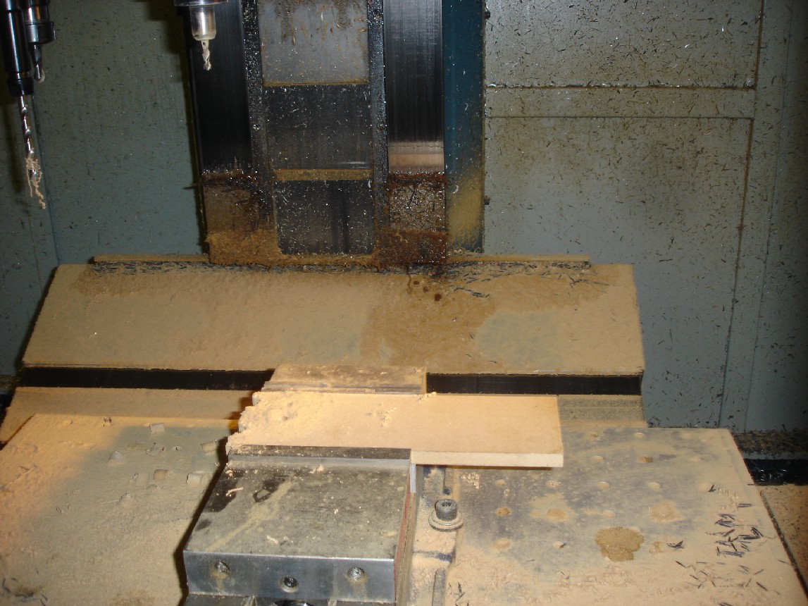
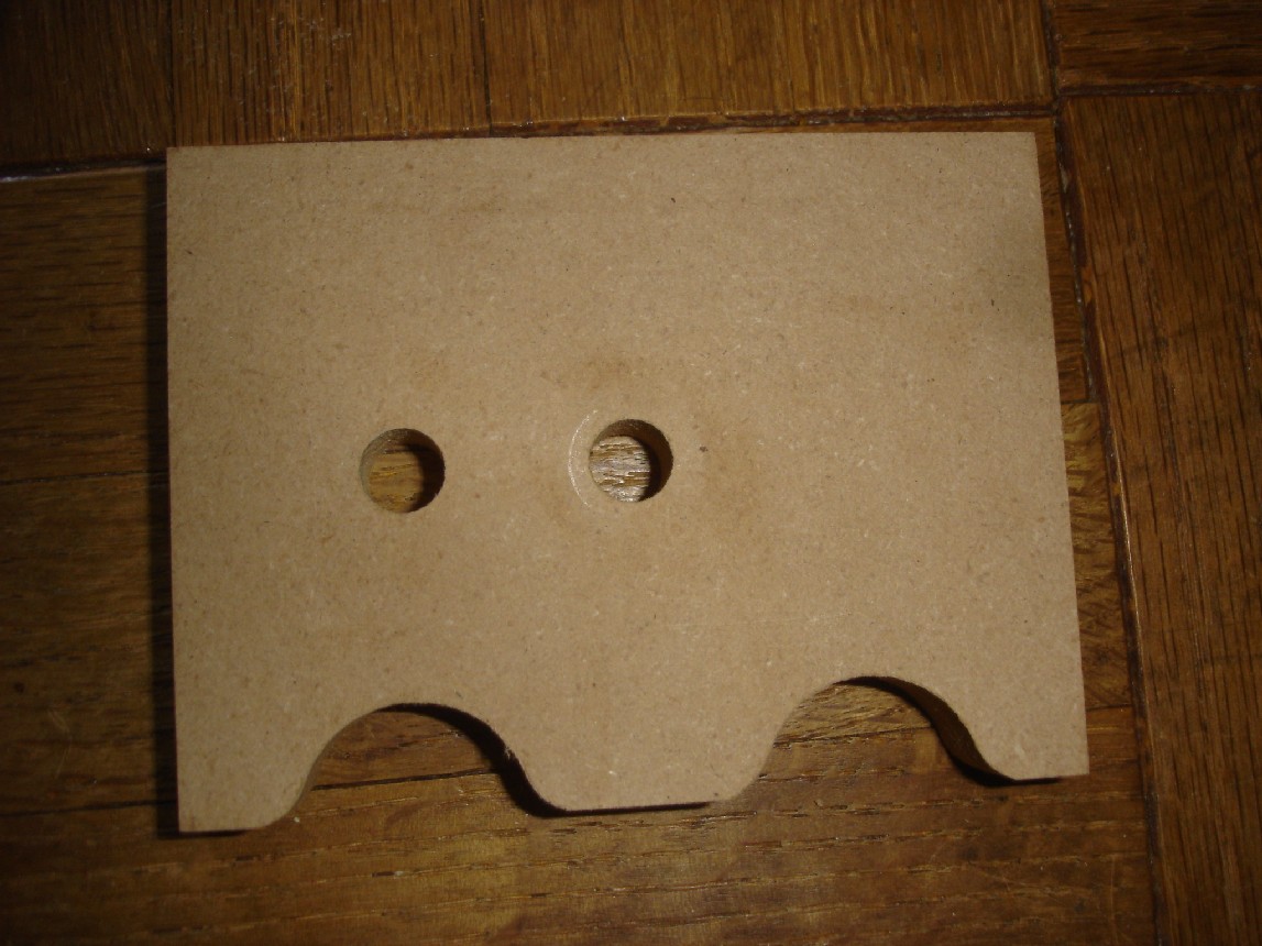
| This is the top of the Z axis being machined in a full size 3 axis mill, it is made from mdf. | ||
 |
||
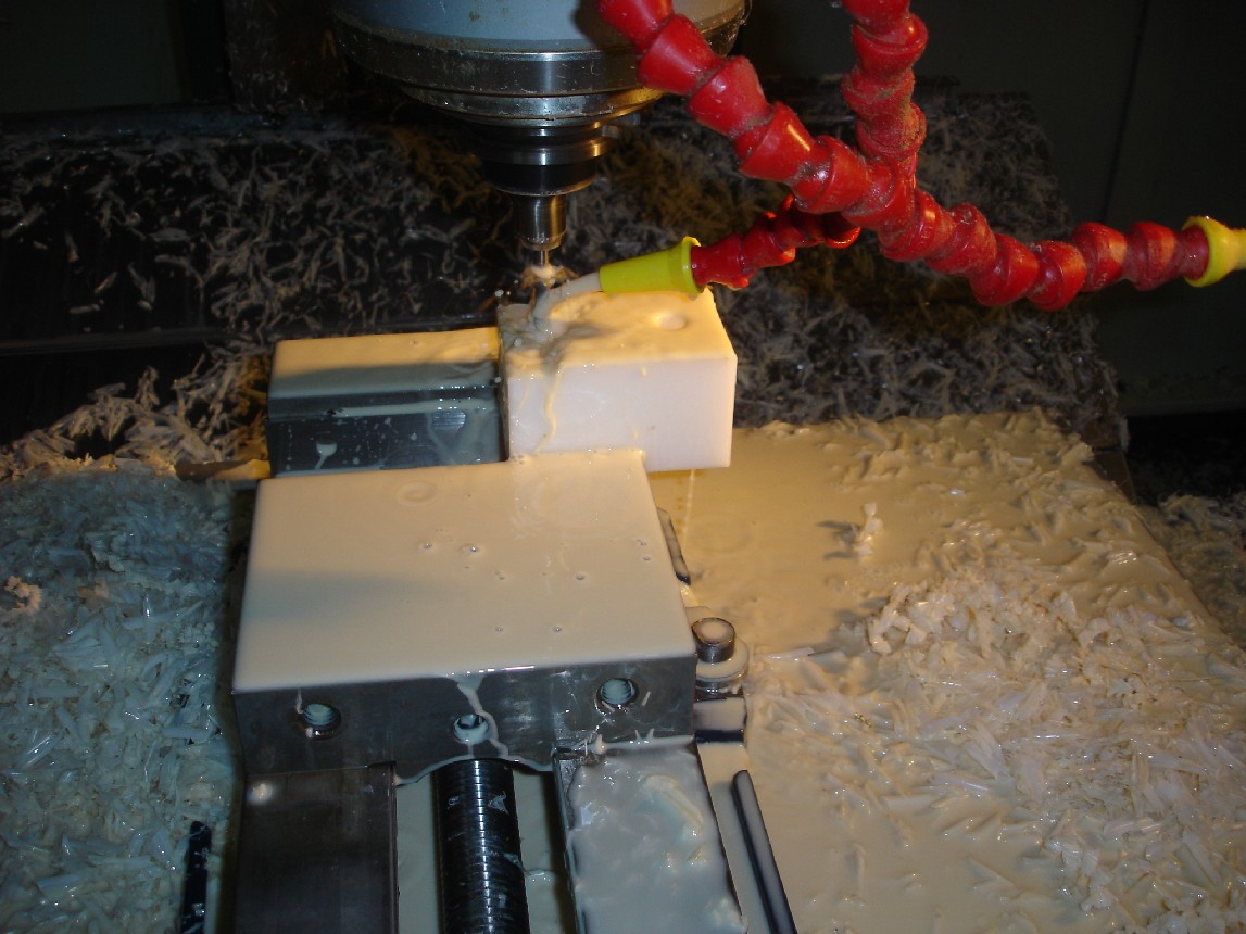
| The part being machined from polyethylene plastic is the tool holder. This is the part into which the Dremel is bolted directly to. | ||
 |
||
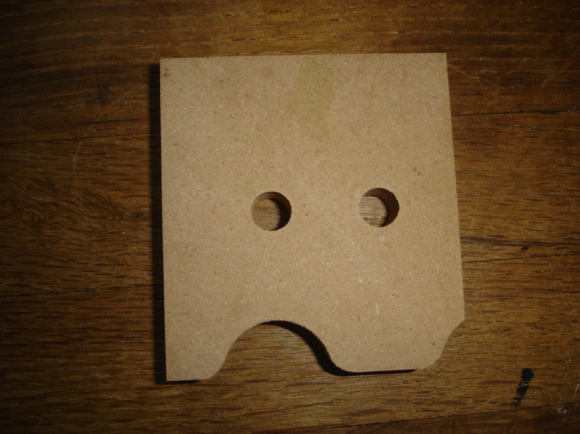
| The completed mdf part of the Z axis stack you can see that this one is the shorter one compared to the one below, this is due to drawer slides needing to be able to clear the Z axis stack. | ||
 |
||
| The full size stack piece that will be laminated together with wood glue. The curves you see on the back are there for counterweights in case the motor for the Z axis is not strong enough to lift the Dremel. | ||
 |
||
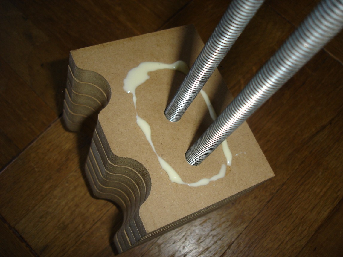
| this is how I laminated them all together put some wood glue and clamp them together with the threaded rods that will go through them. As you can see I only laminated the stack separately from the top arm of the mill and the base of the mill, this is due to me being able to add height or change out parts more easily if I need to. | ||
 |
||
|
|
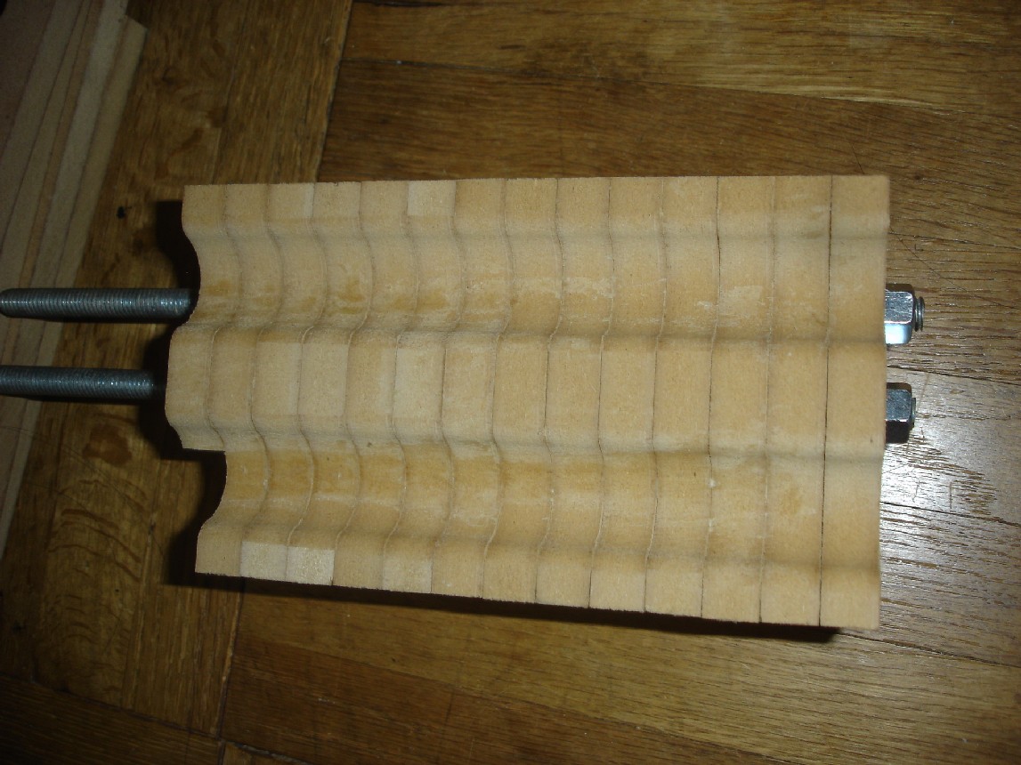
The completed laminated part looks like this once it is clamped and dries. | |
 |
||
|
|
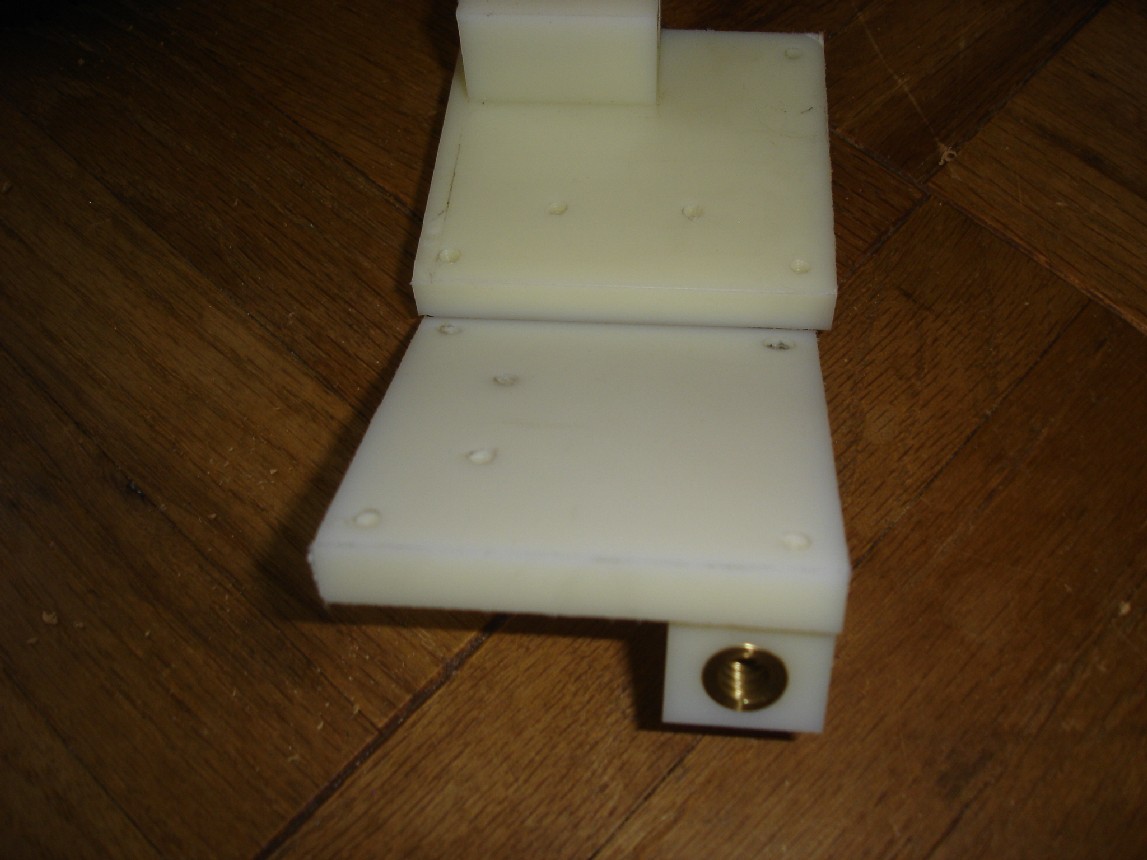
These are the moving screw drives that will ride on top of the 3/8" acme rods. you can see that there is a brass insert for the thread but I'm sure that if I had tapped it directly into the nylon material it would be a nice tight fit as well. This part was cut with a CNC as well, but if I didn't have this material I would have made it out of some sort of hardwood like oak or maple. | |
 |
||
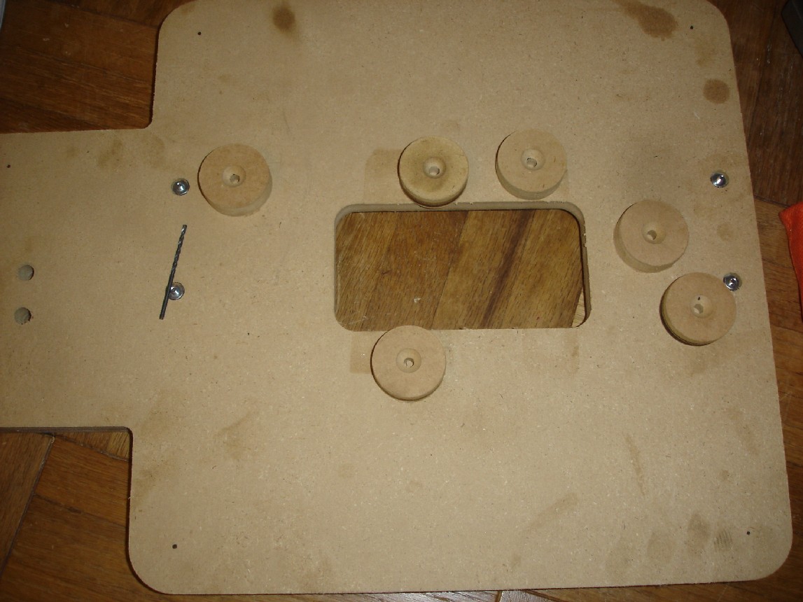
| Since the machine was originally designed so that it sits flat on the ground it did not take into account that the nuts of the Z axis bolts would need to be counter bored. So instead of counter boring I decided to add feet to the machine. | ||
 |
||
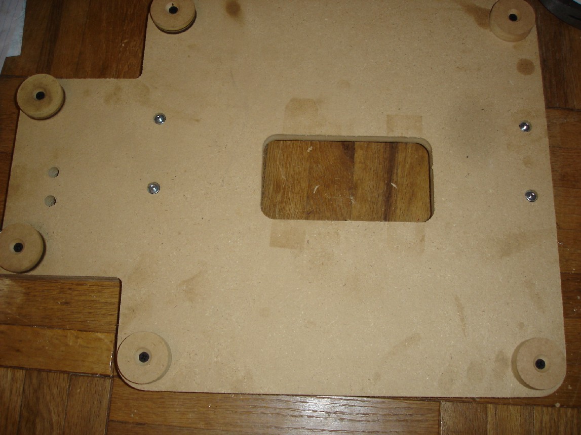
| I had used a hole saw kit to make the feet which made nice round circles with a hole already in the middle from the guide drill bit that is with the hole saw. After the circles were complete I countersunk them so that the screws holding the feet to the base wouldn't stick out. After picking out some short drywalls screws to use i mounted them to the base. | ||
 |
||
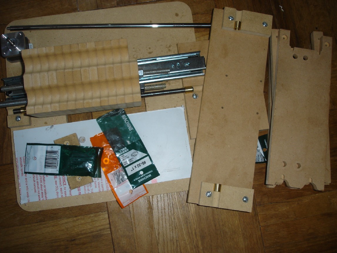
| These are a majority of the parts shown that were used in the assembly of the structure of the CNC mill. This is before I had laminated the Z axis arm the extends out to hold the Dremel. | ||
 |
||
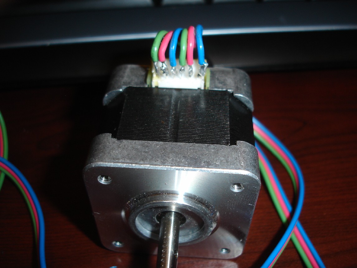
| Since the motors I had purchased on Ebay did not have specs or connectors with some wires on them, I had to solder directly on to the pins. I grabbed some spare wire I had around and soldered them separating the coil windings by color for easier identification later. | ||
 |
||
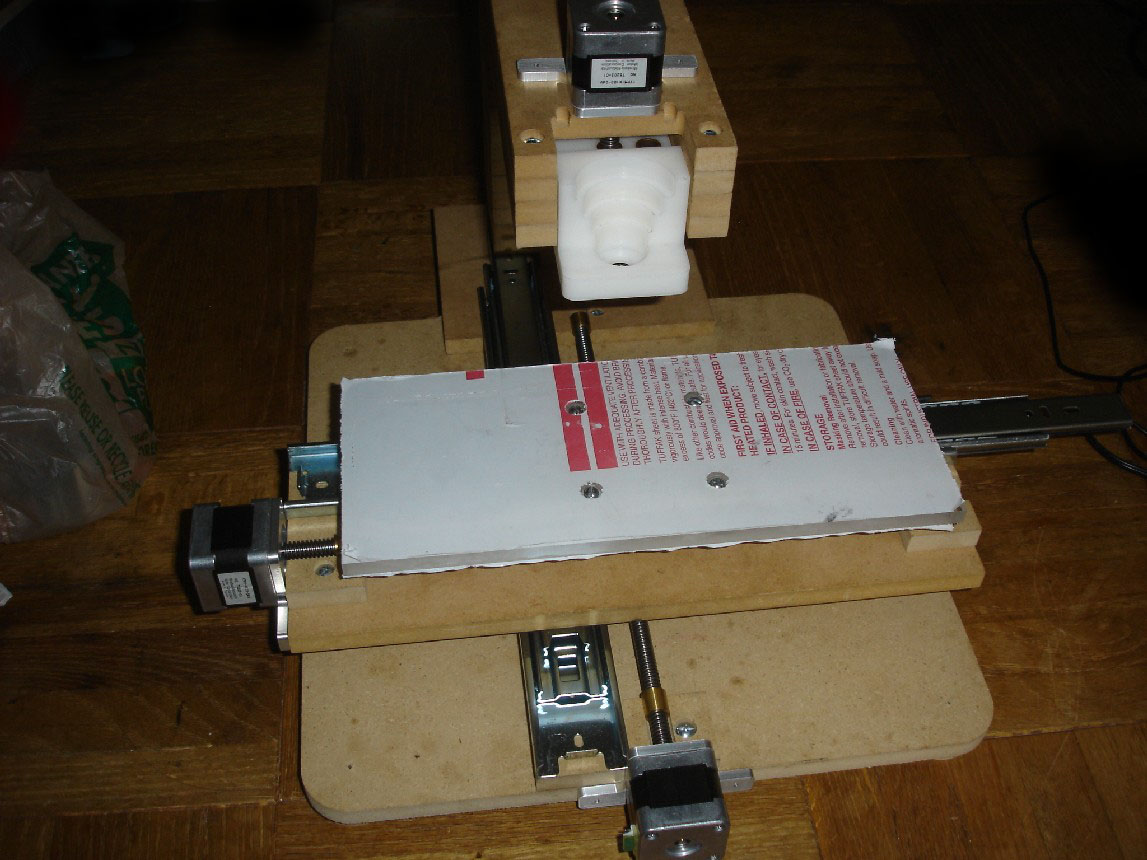
| Once I had the parts assembled I saw an inherent flaw in the design this was with the drawer slides they rocked back and forth too much since the primarily design to function in the vertical position. Using 2 slides instead of 1 would help alleviate the problem but not solve it completely. Since I all the major components already fabricated I decided that once the mill was up and running I would gradually fabricate non essential parts to replace but for now I needed new parts for functionality. | ||
 |
||
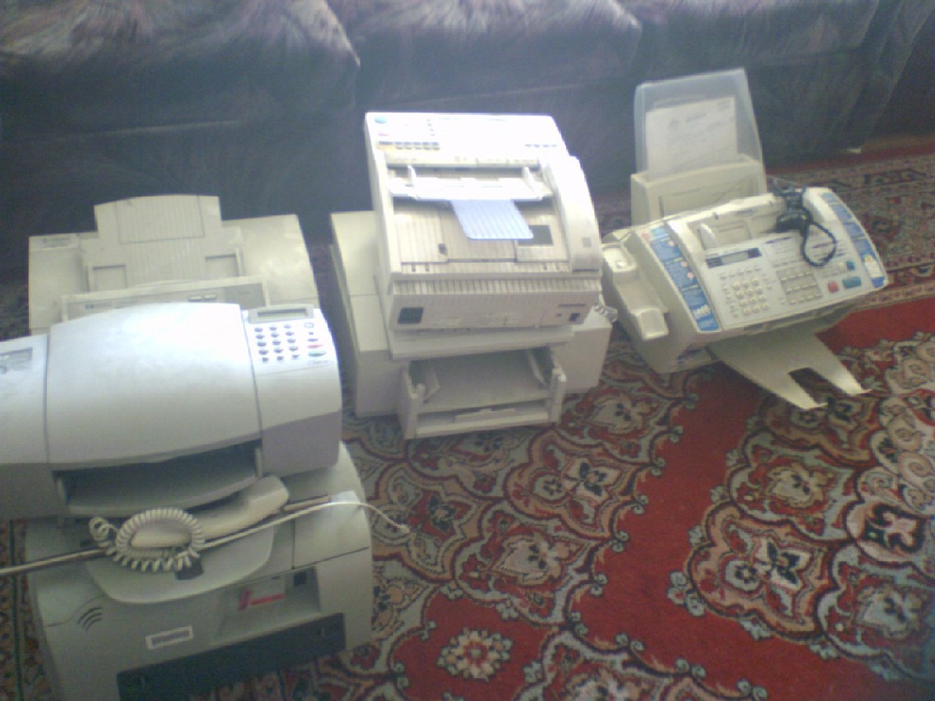
| I had decided that linear rails would be the most effective for smooth precise linear motion. so instead of spending about 20 dollars a rail I looked on Craigslist.org and repair places for old printers, faxes, and scanners, because they would not only provide me with the rails but bushings and a lot of cool motors and switches. After several hours disassembling 8 printers I had matching pairs of rails. It would have been ideal to have the same printers so that I would only need 4-5 but all the extra parts might come in handy for a later project. | ||
 |
||
|
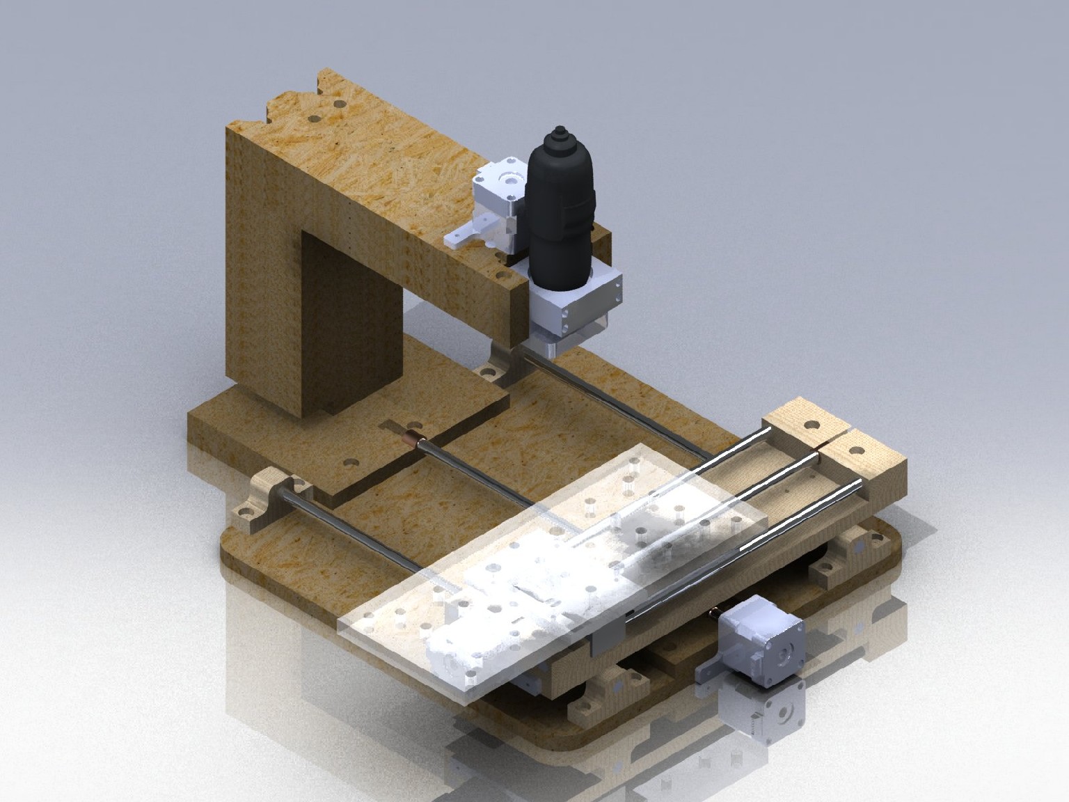
This is the design that I came up with that would make use of the rails instead of the drawer slides. It called for 5 new types of parts since it is fabricated by CNC it is not difficult to make duplicate parts but in all there were 10 new parts. Listed as follows: 4 x X-axis rod holders that are bolted to the base 2 x bushing blocks that will slide on X-axis 1 x Y-axis base (I redid this so that I could redo the material and hole locations) 2 x Y-axis pillow blocks that the rails and acme rod slide into 1 x Y-axis new screw drive needed to be redone so that the rails and acme rod are all connected as one peice.
The wood parts above were made from Maple a 4" x .75" x 48" peice for $14 at Home Depot.
Those were my essential redesigned changes. These are the new Solidworks plans for it - 3.5Mb |
||
 |
||
| This is the new animation of the movements with the updated design. In addition to displaying the movements it also displays the machine from various angles. | ||
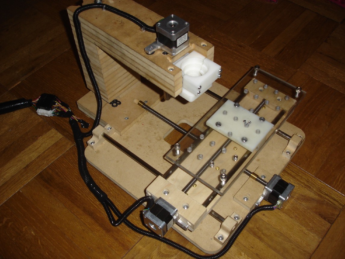
| This is a picture of the completed design as it is fabricated and assembled. So the mechanical component is essentially complete, now it's on the the driver, power, and control of the setup. | ||
 |
||
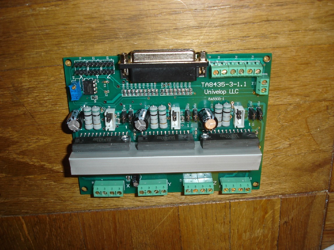
| This is the driver board (Univelop TA8435-3-1.1) that i purchased on ebay for $50. After looking at the cost of parts for the driver board that was built for my last cnc project I found it simpler and more cost effective to purchase a prefabbed board. | ||
 |
||
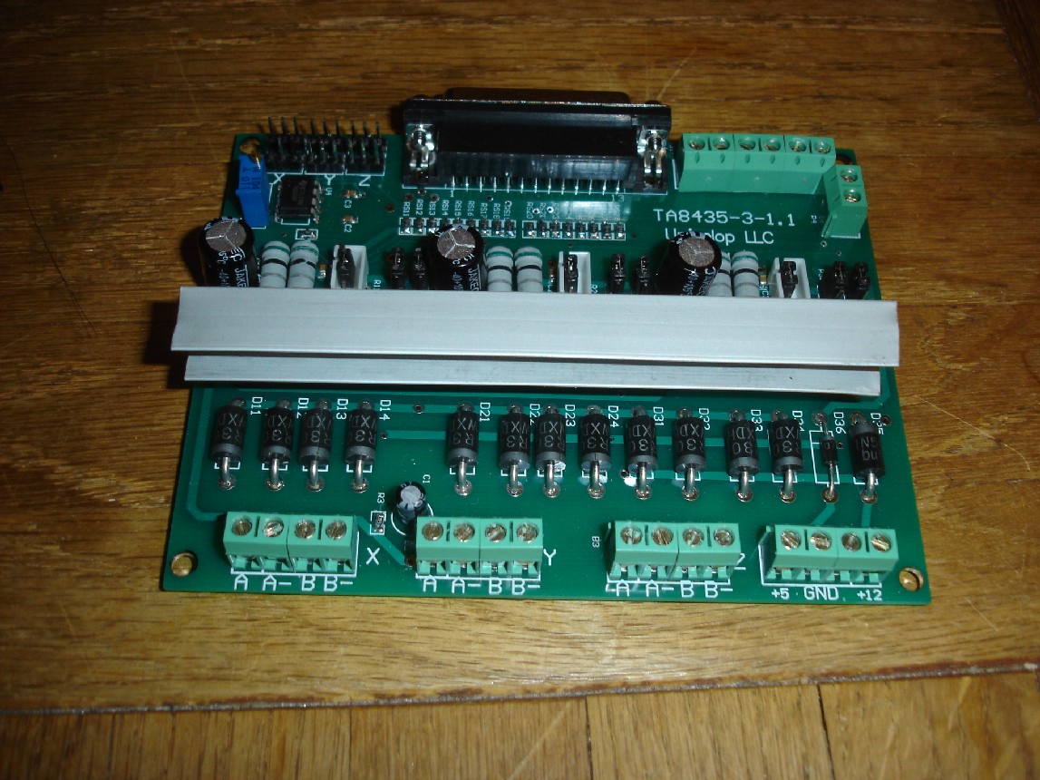
| As you can see these heat sinks are very thin and upon powering up the motors with the driver I found that they get very hot after only a short time. I knew I had to either put a fan on the heat sinks or upgrade them to a larger size to effectively move heat away from the driver board. | ||
 |
||
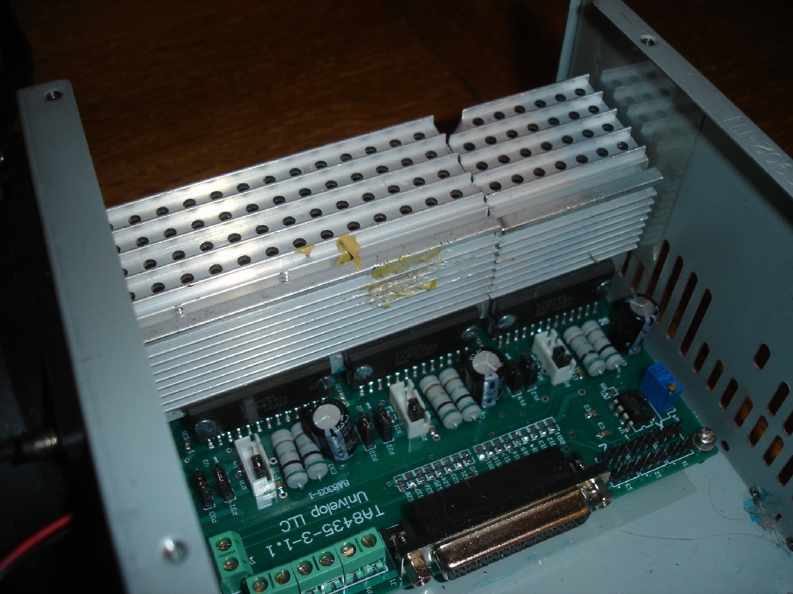
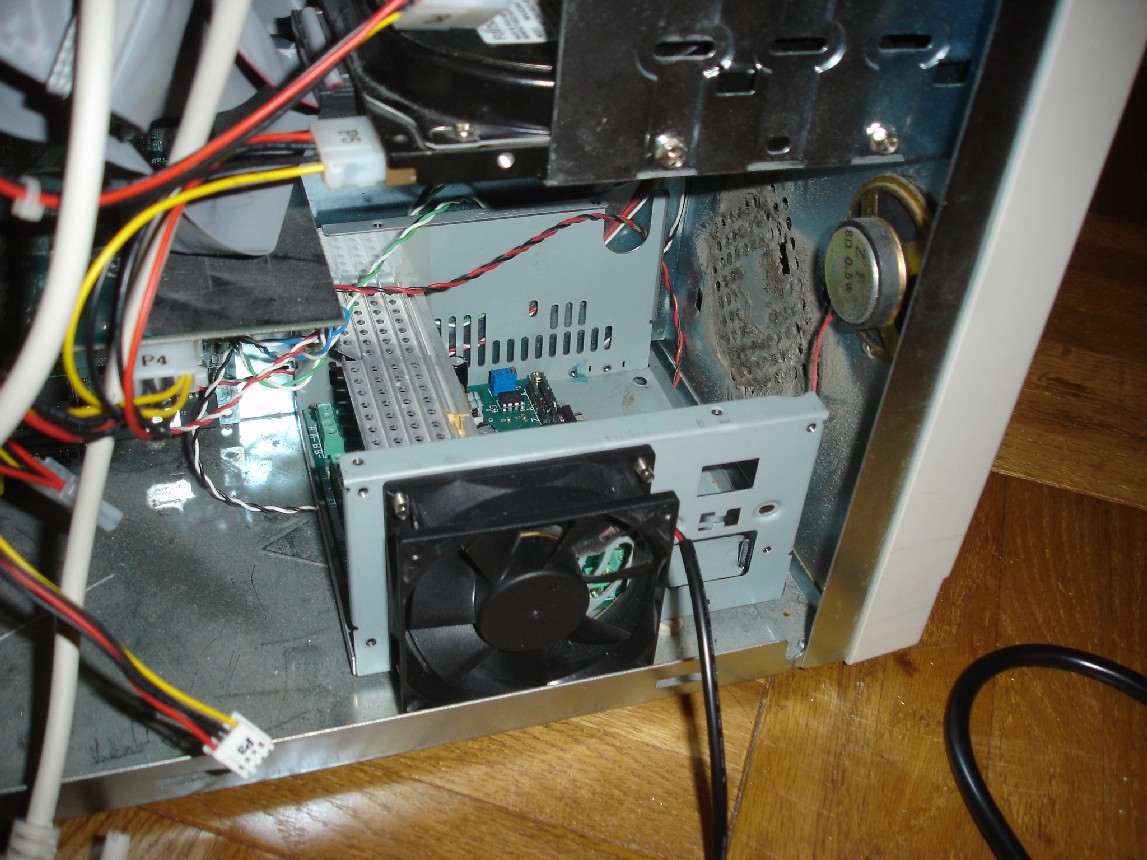
| I had a burnt out ATX computer power supply which is the perfect source for a heat sink, fan, and case to house the unit in. I moved the fan that was on the inside of the case to the outside and drilled new holes so that the heat sinks fit perfectly to the driver chips. I had also modified the case so that the board mounts to it since the power supply mounting is different. | ||
 |
||
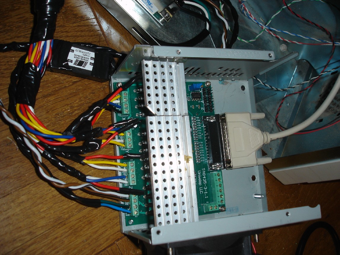
| This is the unit hooked up with the motors, parallel port, and power supply. The model of board that was purchase is designed to work with bipolar motors, but if the center tap coils aren't used the 6 wire configuration works, which is what I did. Since I plan to have a manual encoder for the motors later I decided to run all of the wires that come off of the motor anyway. The 24V power supply needed to drive the motors was purchased on Ebay from Hubbard CNC for $30, although if I had additional spare PSU I would most likely have used that instead. | ||
 |
||
| I used an old computer to run the whole setup, a 500mhz Pentium to be exact, although the CNC control software (mach3) recommends at least a 1GHz CPU the 500 is all I had handy and it runs stable enough. So in an effort to make the machine as compact and portable as possible I wanted to ensure that the cnc driver parts and power supply all fits into the case, which it did, snuggly. | ||
 |
||
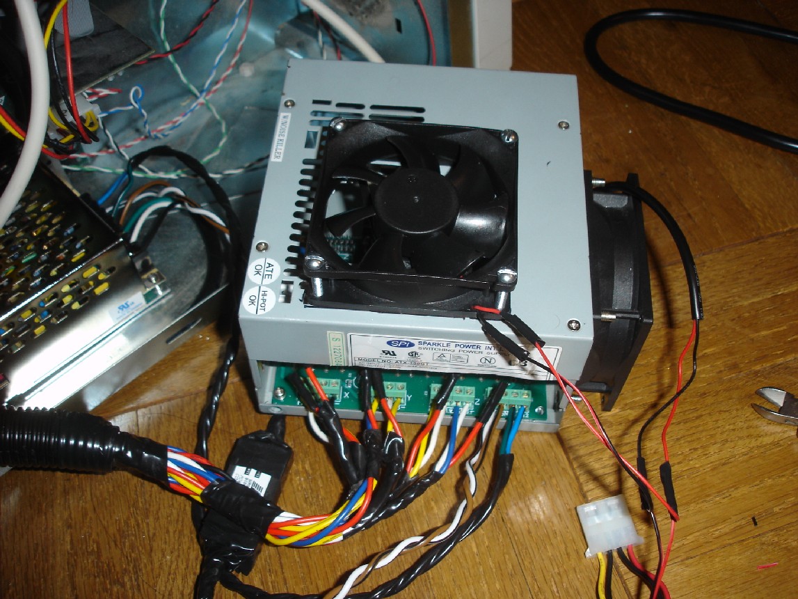
| I had an additional fan lying around so for additional cooling of the driver board I mounted the fan to the top of the PSU case and cut off the sides so that air flows freely in and out. Upon running the board for over an hour the heat sinks stayed nice and cool, the motors on the other hand got pretty warm, so I'll have to do something about that later but that's another story. | ||
 |
||
|
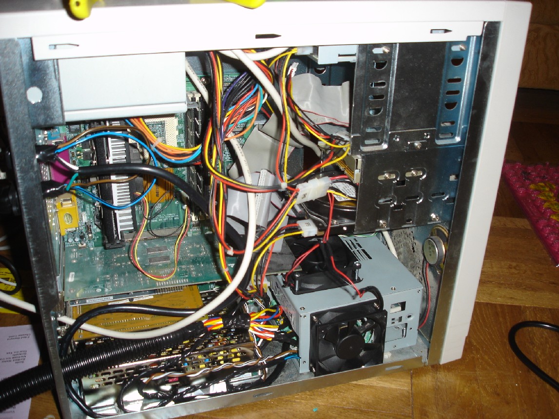
this is the complete setup inside the computer case
and as you can see everything fits very snuggly into it. The 24V power
supply sits directly below the video card inside the case. The next steps
are to try to get the cases side panel to fit on once I cut out a hole for
the fan. You can see the loomed up control wires running out of the case
to the motors. I added connectors to the mill so that I could quickly
detach the computer from the machine for easy transport, since portability
is very important to me. The total running cost at this point is about $120 since a large majority of my parts were recycled from something else. If it wasn't for recycled parts it would most likely run in the $250 range which is still a very decent price for a working CNC mill. |
||
 |
||
| This is the operation of the CNC micro mill before any major tuning is done. I got the basic tuning done so that the dimensions and movement are done correctly but still need to add limit switches. | ||