 |
|
|
|
Electronic Circuit Diagrams
(Click on the image to enlarge it)
|
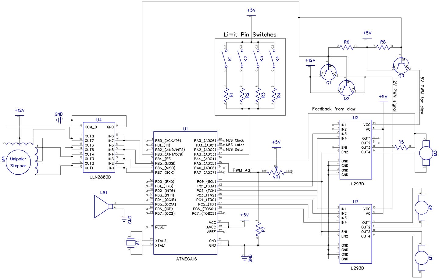 Claw Game Circuit - The circuit which I
designed to the left, shows the basic control and interface of a claw
machine that one would find in a local shopping center or arcade. It
interfaces to a single ATMega16 chip in order to read commands from a NES
controller and output signals to the x/y/z axis as well as a 4th motor
controlling the claw open/close command. I will eventually post the
working code and the finalized circuit diagram.
Claw Game Circuit - The circuit which I
designed to the left, shows the basic control and interface of a claw
machine that one would find in a local shopping center or arcade. It
interfaces to a single ATMega16 chip in order to read commands from a NES
controller and output signals to the x/y/z axis as well as a 4th motor
controlling the claw open/close command. I will eventually post the
working code and the finalized circuit diagram.(Click on the image to enlarge it) |
|