In Engineering 10B we were assigned to come up with
an adjustable ramp so that we could aim a vehicle and guide it precisely
into a skee ball target for various point values. I undertook the task of
designing and fabrication the lifters for making the ramp adjustable, to
make matters more difficult, everything had to be made from a natural
material, so metals and plastics or other composites were out of the
question. I though of a peg and slot style design but then realized that
it is too inaccurate since each increment relies on where each spot is
drilled. Every animation and drawing here is done in Solidworks and
rendered in Photoworks.
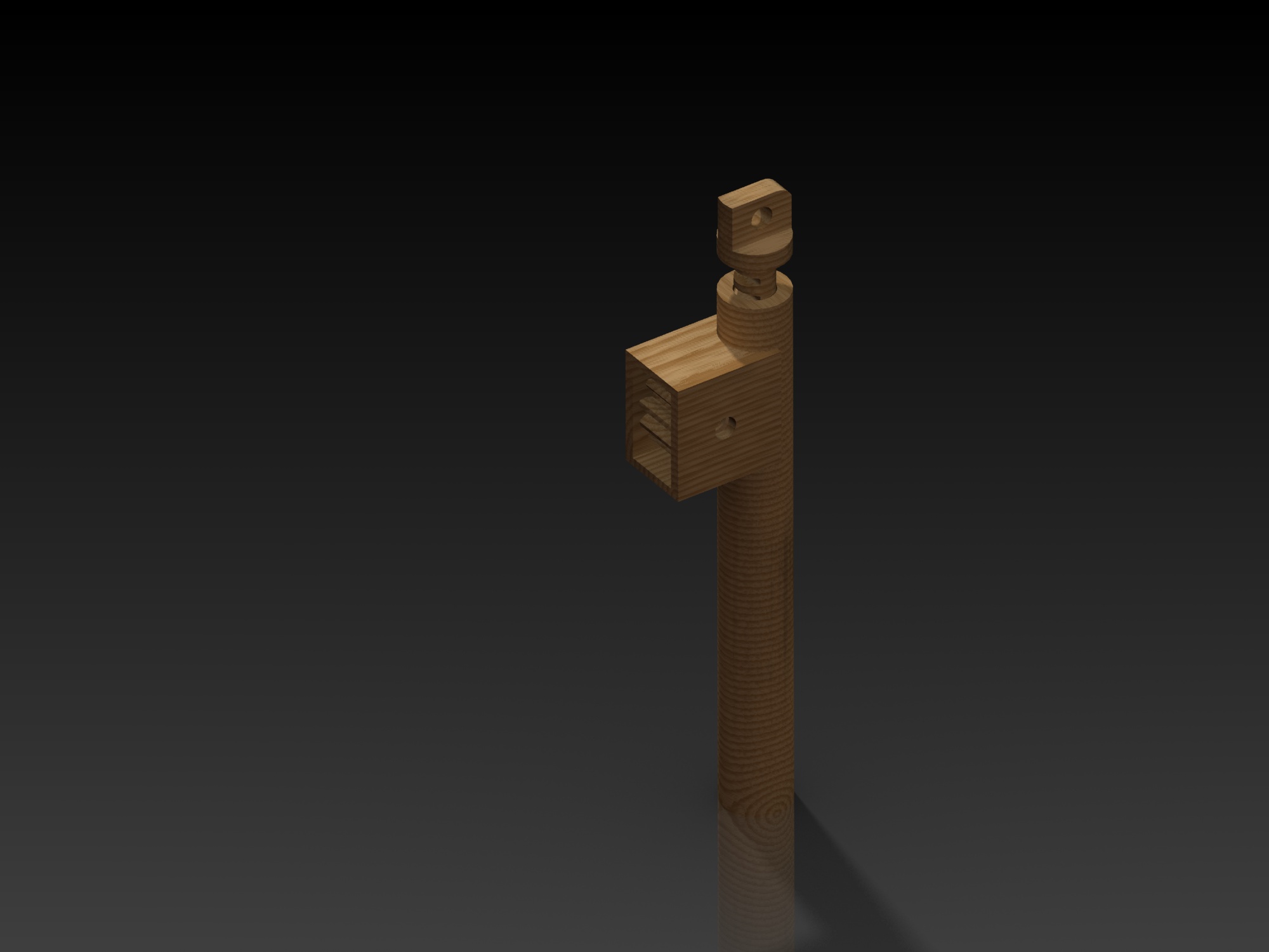
The lifter design that I ultimately went with was a
rack and pinion design. This allows for maximum homing in of the correct
angle to propel the launch vehicle to the center of the target. The
drawing here depicts what one side of the lifter would look like upon
completion. There will ultimately be 2 lifters and a connecting rod
between them.
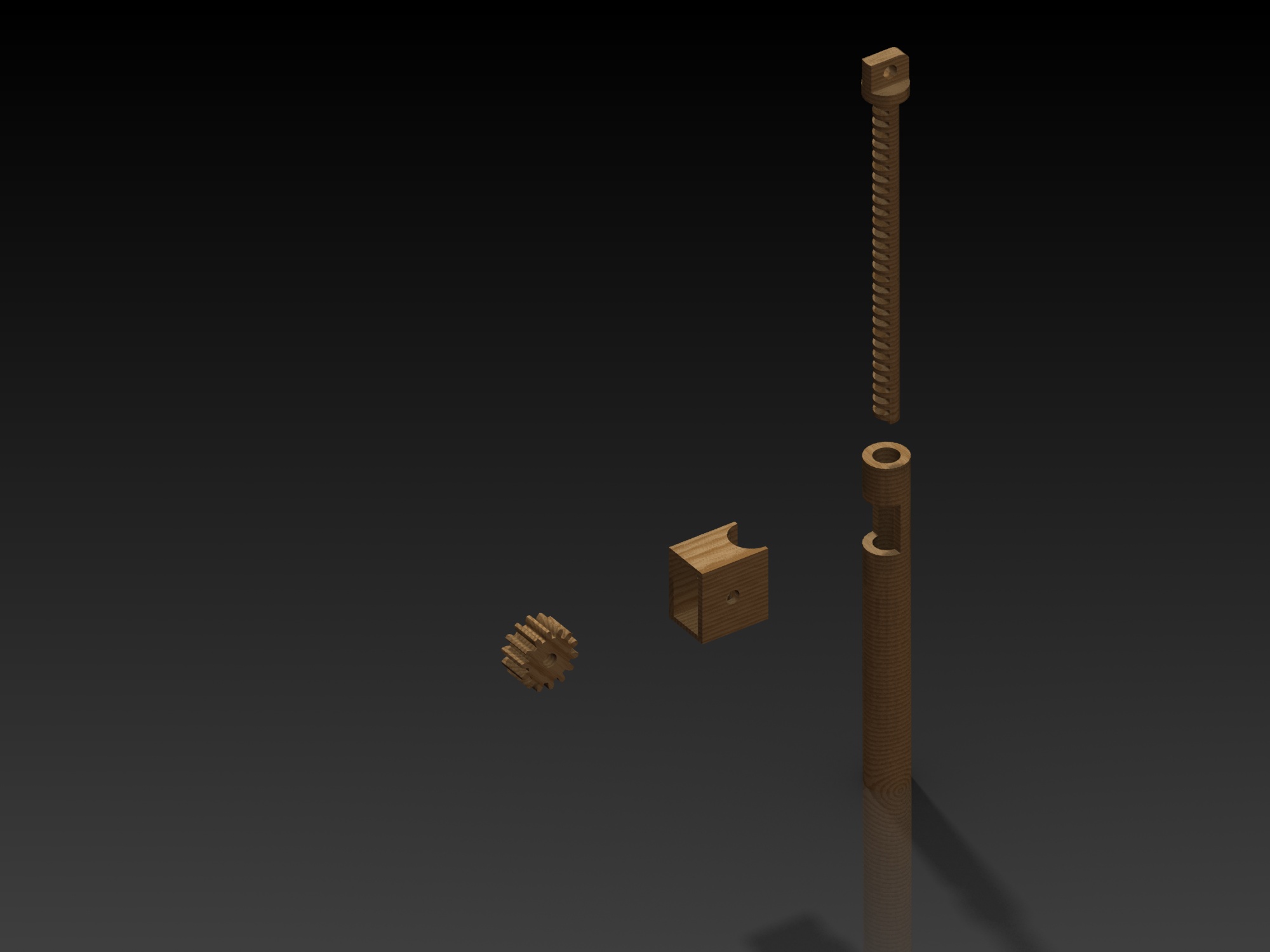
This is the exploded view of the components to
represent how everything assembles together once the parts are fabricated.
It clearly shows the sprocket gear and the rack that will be moving the
lifter up and down.
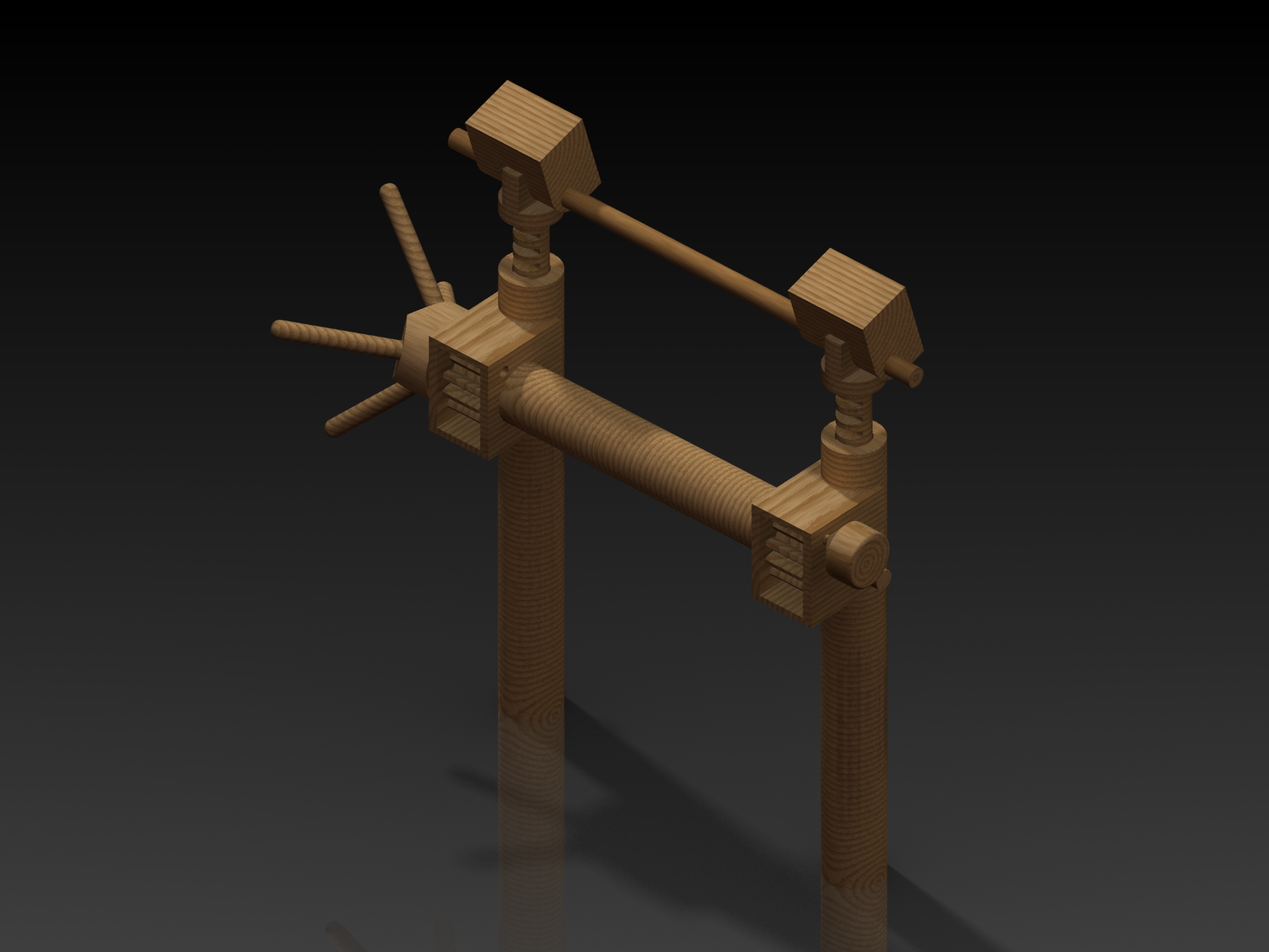
The completed assembly will look something like
this. notice that the gears are joined together by a solid wooden
connection rod so that the level of the lifters will be level with respect
to each other. Also the knob that will assist in being able to crank the
rack up and a stopper to hold the assembly in place once it is position in
manor that we chose. The square pieces on the top of the racks are the
pieces that will slide against the ramp and provide a sturdy and large
contact area.
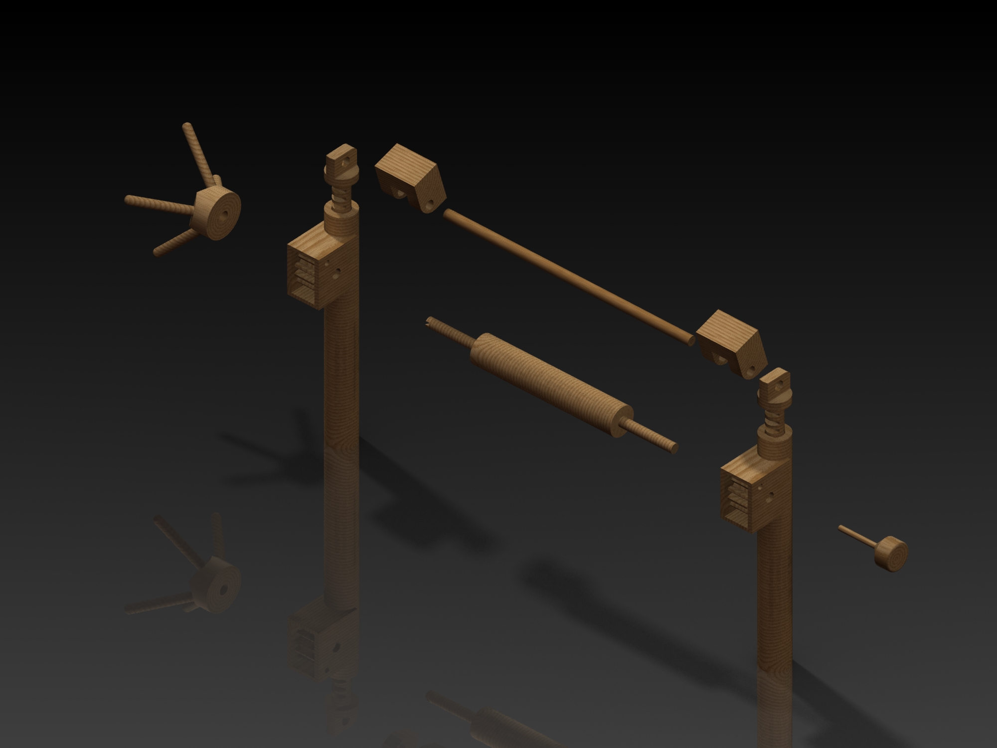
The exploded view shows how the other pieces are
assembled with respect to the lifters. the lifters are tied together at 2
points to minimize any unevenness that could possibly occur while it is
being cranked up or down during adjustments.
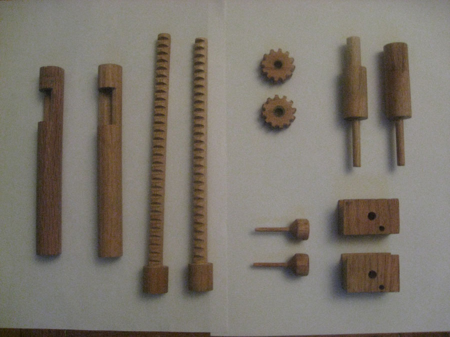
Here are the pieces after some manual and CNC
machining is done to some raw oak material (the crank handle and support
is not pictured). There are still several areas that need to be finished
by hand then the assembling begins.
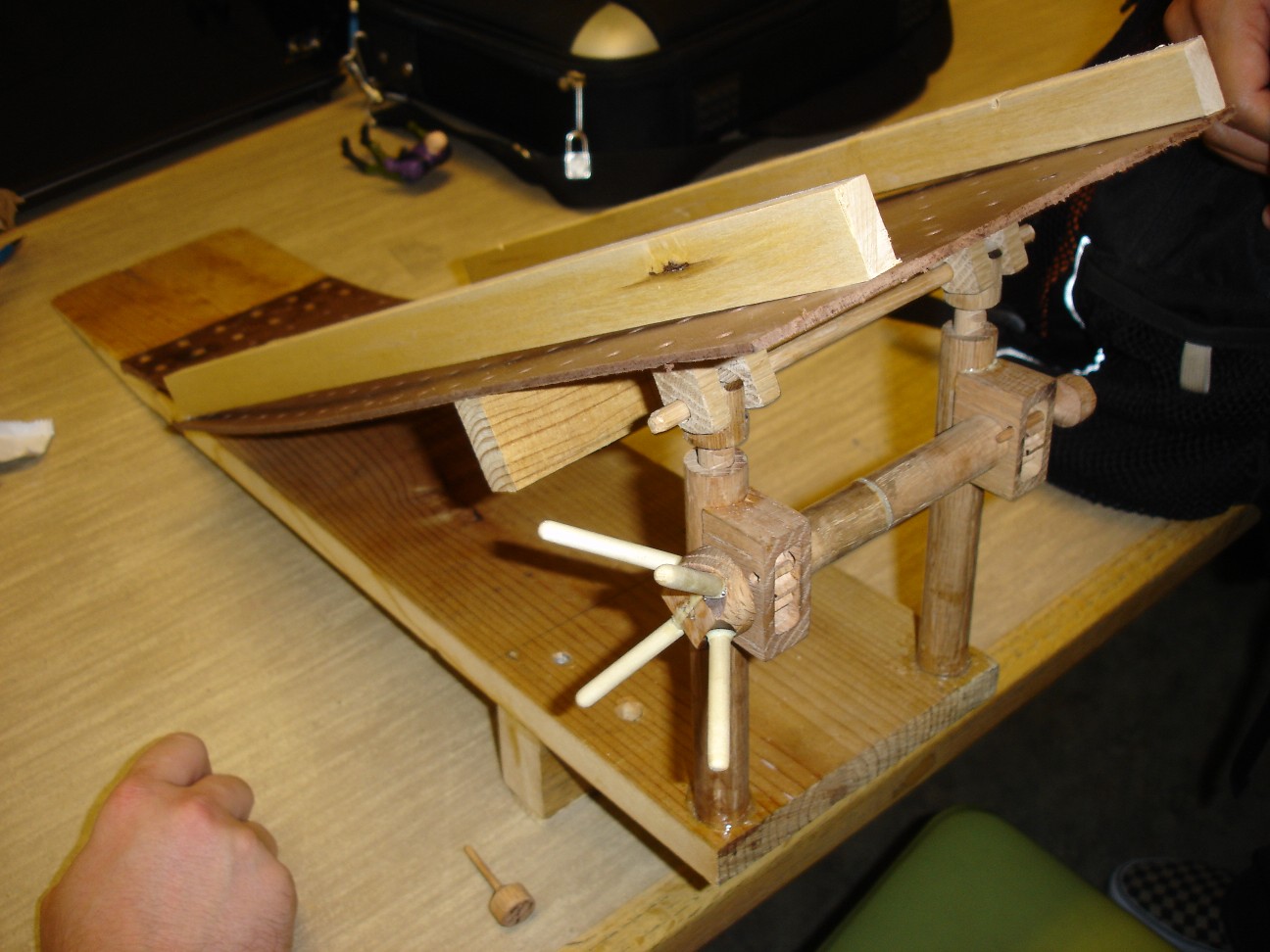
Once the ramp and the lifters are assembled
separately then joined together into one structure the result looks like
this. The ramp is made of a pegboard material and you can clearly see the
guides in place to guide the launch vehicle into any location that we want
it to go.
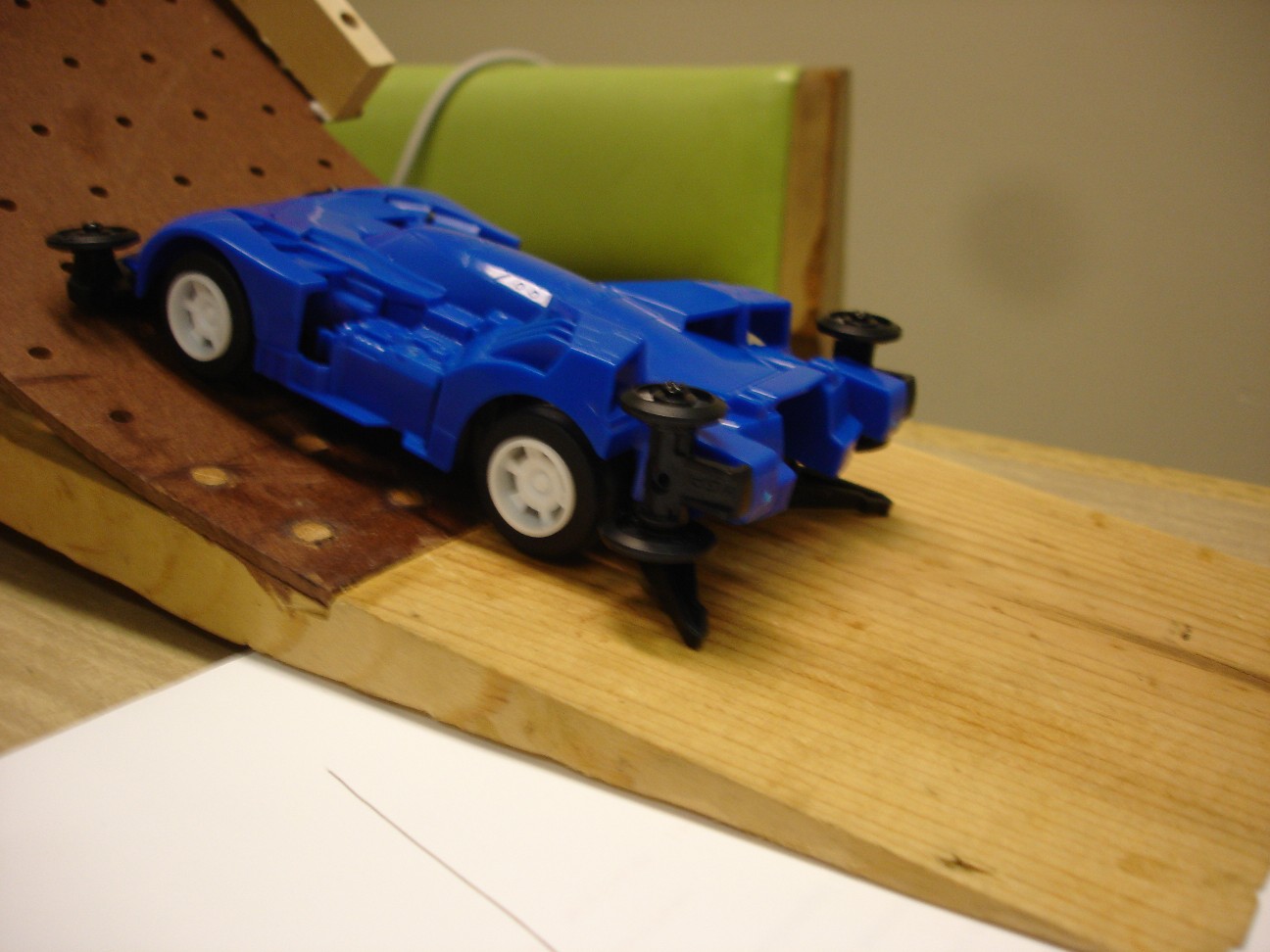
This is the launch vehicle, we decided to go with a
vehicle that already has side rollers so that there is minimal frictional
loss before the vehicle makes it to the launch ramp. As you can see in the
picture the grounding tabs at the rear of the vehicle cause the wheels to
life off of the ground at one point on the ramp. We ended up trimming the
grounding tabs off to avoid that problem.
This is the exploded view animated to maximize the
visibility, as well as clearly demonstrate how the lifter is disassembled
and assembled.
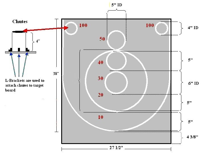
This is the target into which the launch vehicle
had to land in order to score points. Our groups design ended up scoring
the first in the 4 groups in our section and second overall in the total
points across the other class sections. We learned that there is a certain
amount of randomness during the flight and position of the vehicle;
so many times it bounced off of the top of the target.

